What are Acceptable No Load Loss Values for Power Transformers?
Learn acceptable no load loss values for power transformers, typical ranges by kVA rating, testing accuracy tips, and how Wrindu supports reliable evaluation.
No load loss is a key performance indicator for power transformers. It directly affects energy efficiency, operating cost, and compliance with technical standards. Engineers, utilities, and manufacturers often ask what level of no load loss is acceptable for a given transformer rating. Understanding acceptable no load loss values helps users judge transformer quality and verify test results with confidence.
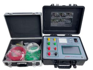
Click the picture to know more about Wrindu Transformer No load and load loss Tester.
What Is Considered Acceptable No Load Loss?
Acceptable no load loss refers to a loss value that meets design expectations, industry standards, and contract guarantees. It does not mean one fixed number for all transformers. Instead, acceptable no load loss depends on transformer size, core design, material quality, and kVA rating. Engineers usually compare measured results with typical industry ranges and guaranteed values to decide acceptance.
How Does kVA Rating Affect No Load Loss Values?
Transformer kVA rating has a strong influence on no load loss. As transformer size increases, core volume grows and total core loss increases. However, no load loss does not rise in direct proportion to kVA. Larger transformers often use better core materials, which helps control loss growth. This is why acceptable no load loss must always be evaluated in relation to kVA rating.
What Are Typical No Load Loss Ranges by kVA Rating?
Typical ranges help engineers quickly judge whether results look reasonable during testing. The values below represent common industry expectations, not fixed limits.
For small distribution transformers around 100–500 kVA, acceptable no load loss often falls between 200 W and 800 W.
For medium transformers in the 630–2000 kVA range, typical no load loss usually ranges from 800 W to 3 kW.
For larger power transformers above 2500 kVA, no load loss commonly exceeds 3 kW and increases with rating and voltage class.
Actual acceptable no load loss must always align with the guaranteed value stated by the manufacturer.
Why Should Engineers Compare Results to Typical Ranges?
Comparing test results to typical ranges helps engineers detect abnormal conditions early. If measured no load loss exceeds the expected range, it may indicate core issues, incorrect test setup, or measurement error. If the value falls far below typical levels, engineers should also confirm instrument accuracy to avoid false readings. Typical ranges provide context, not final judgment.
How Do Standards and Guarantees Define Acceptance?
Standards such as IEC and IEEE focus on comparison with guaranteed values rather than fixed limits. A transformer meets acceptance criteria when measured no load loss stays within the guaranteed loss plus the allowed tolerance. Typical ranges support technical judgment, but contractual guarantees determine final acceptance.
How Does Measurement Accuracy Affect Acceptable No Load Loss?
No load loss involves low current and low power factor. These conditions magnify measurement errors. Poor instrument accuracy can make acceptable no load loss appear too high or too low. That is why engineers must use dedicated transformer test systems. Wrindu transformer testers offer high resolution and stable phase measurement, helping users confirm acceptable no load loss values with confidence.
What Common Questions Do Engineers Ask About Acceptable No Load Loss?
Does a Higher-Than-Expected No Load Loss Always Mean Transformer Failure?
No. A higher value does not always mean failure. Test conditions, voltage stability, and residual core magnetism often affect the result and can increase measured no load loss.
Do Typical No Load Loss Ranges Replace Guaranteed Values?
No. Typical ranges only provide reference. Engineers use them to guide judgment, but guaranteed values and contract limits define final acceptance.
Can General Power Meters Be Used for No Load Loss Testing?
Usually no. General power meters struggle at low power factor and low current, which leads to inaccurate no load loss results. Dedicated transformer test systems work better.
How Does Wrindu Support No Load Loss Evaluation?
Wrindu focuses on transformer testing and power measurement solutions. Our no load loss test systems deliver stable results across a wide kVA range. High accuracy, strong anti-interference design, and user-friendly operation help engineers verify acceptable no load loss during factory tests and site inspections. Wrindu equipment supports confident decision-making for high-intent technical users.
