Transformer Turns Ratio vs. Voltage Ratio: What’s the Difference and Why It Matters
Learn the key differences between transformer turns ratio and voltage ratio, master accurate testing per IEC 60076-1 & IEEE standards, and avoid common measurement errors.
If you work with power transformers, you’ve likely heard both transformer turns ratio andtransformer voltage ratio thrown around when discussing transformer ratio testing. Many technicians use the terms interchangeably—but they are not the same. Mixing them up can lead to faulty readings, misdiagnosed issues, and non-compliance with IEC 60076-1 & IEEE C57.12.90 standards. Below, we break down their definitions, how they relate, and why clarity matters for accurate, reliable testing.
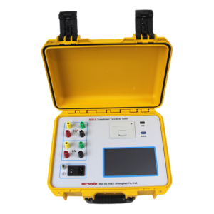
Click the image to know more about Transformer Turns Ratio Tester.
What Is Transformer Turns Ratio?
The transformer turns ratio is a fixed, physical ratio of the number of wire turns in the high-voltage (HV) winding compared to the low-voltage (LV) winding of a transformer. It is a design constant—etched into the transformer’s blueprint and printed on its nameplate—and does not change during operation.
Expressed as a simple formula:
Turns Ratio (TR) =NHV/NLV
Where NHV = number of turns in the high-voltage winding, and NLV = number of turns in the low-voltage winding. This ratio dictates how the transformer steps voltage up or down, and it is the baseline for all compliance checks, including the strict ±0.5% tolerance required by global standards.
What Is Transformer Voltage Ratio?
The transformer voltage ratio is a measured ratio of the applied voltage on the HV winding to the induced voltage on the LV winding during testing. Unlike the fixed turns ratio, this value can shift slightly due to operating conditions, magnetic losses, wiring errors, or equipment limitations.
Its formula mirrors the turns ratio but uses real-world voltage readings:
Voltage Ratio (VR) =VHV/VLV
Under ideal, no-load conditions (perfect magnetic coupling, zero losses), the voltage ratio will match the turns ratio exactly. In real field or factory settings, minor deviations are normal—but any gap outside the ±0.5% tolerance signals a potential problem.
Key Differences Between Turns Ratio & Voltage Ratio
|
Characteristic
|
Transformer Turns Ratio
|
Transformer Voltage Ratio
|
|---|---|---|
|
Nature
|
Fixed physical property (design-specific)
|
Measured, variable reading (test-dependent)
|
|
Source
|
Transformer nameplate & design specs
|
Calculated from live test voltages
|
|
Impact of Losses
|
Unaffected by magnetization or load losses
|
Slightly skewed by magnetic losses & load effects
|
|
Compliance Role
|
Reference standard for pass/fail testing
|
Metric used to compare against nameplate turns ratio
|
Why This Distinction Matters for Ratio Testing
Transformer ratio testing exists to confirm that the measured voltage ratio aligns with the nameplate turns ratio within the allowed ±0.5% tolerance. When the two values diverge beyond this limit, it points to issues like shorted turns, faulty tap changers, or winding damage.
Technicians often make the mistake of treating voltage ratio as a perfect substitute for turns ratio, which can lead to false passes or unnecessary repairs. Understanding the difference helps you:
-
Avoid misinterpreting minor voltage fluctuations as critical faults
-
Calibrate test equipment to account for magnetic losses
-
Stay compliant with IEC and IEEE testing requirements
-
Extend transformer lifespan by catching real issues early
To minimize discrepancies, always test at rated (or lower) voltage and frequency, demagnetize windings before testing, and use high-precision equipment to reduce measurement noise.
How Wrindu Testers Stand Out in Turns & Voltage Ratio Measurement
Wrindu portable ratio testers are engineered to eliminate the guesswork between turns ratio and voltage ratio, delivering lab-grade accuracy in both field and factory environments. Here’s what sets them apart:
-
0.03% Ultra-High Accuracy: Far exceeding the ±0.5% standard tolerance, Wrindu testers capture tiny deviations between measured voltage ratio and nameplate turns ratio, so you never miss a red flag.
-
Automatic Loss Compensation: Built-in algorithms adjust for magnetization losses and the “half-turn effect,” ensuring voltage ratio readings closely match the true physical turns ratio.
-
Dual Standard Compliance: Fully calibrated to meet IEC 60076-1 & IEEE C57.12.90 requirements, with one-touch testing for both single-phase and three-phase transformers.
-
Instant Nameplate Comparison: Input the rated turns ratio once, and the tester automatically calculates variance, displays pass/fail status, and logs data for compliance reports.
-
Anti-Interference Design: Shielded circuitry reduces noise from nearby equipment, delivering consistent voltage ratio readings even on busy job sites or substations.
Whether you’re performing factory acceptance tests (FAT) or field maintenance, Wrindu testers bridge the gap between theoretical turns ratio and real-world voltage ratio measurement for unbeatable reliability.
FAQs About Transformer Turns Ratio & Voltage Ratio
Q: Can voltage ratio ever be exactly equal to turns ratio?
A: Yes—under ideal no-load conditions with zero magnetic losses, perfect winding alignment, and calibrated test equipment, the measured voltage ratio will match the transformer’s fixed turns ratio. Minor differences in real-world use are normal, but deviations over ±0.5% indicate a problem.
Q: Why do I see a small difference between voltage ratio and nameplate turns ratio during testing?
A: Small gaps are typically caused by magnetization current, winding resistance losses, residual magnetism in the core, or slight test voltage fluctuations. Using a high-precision tester like Wrindu’s models helps minimize these discrepancies and ensures compliance.
Q: Do IEC 60076-1 and IEEE C57.12.90 use turns ratio or voltage ratio for compliance?
A: Both standards use the nameplate turns ratio as the reference and require the measured voltage ratio to fall within ±0.5% of that value. Technicians measure voltage ratio to validate the fixed turns ratio during testing.
Q: Does tap changer operation affect turns ratio or voltage ratio?
A: Tap changers physically adjust the number of active winding turns, so they change the effective turns ratio (and thus the target voltage ratio) for each tap position. You must test every tap to confirm compliance across the full range.
Q: How do I reduce errors when measuring voltage ratio for compliance?
A: Demagnetize the transformer core before testing, use a stable low test voltage (5-10% of rated), avoid nearby electrical interference, and use a precision tester with loss compensation like Wrindu’s portable ratio test kits.
