

3-Point Ground Resistance Test: Step-by-Step Procedure & Best Practices
Learn the complete 3-point ground resistance test procedure, electrode placement rules, working principles, and professional best practices for accurate grounding resistance measurement.
What Is a 3-Point Ground Resistance Test?
The 3-point ground resistance test, also named the fall-of-potential method, is the most widely used and accurate testing technique for measuring the resistance of electrical grounding systems. It is the standard test method for substations, industrial plants, renewable energy stations and various electrical installations worldwide. This method relies on three core electrodes and Ohm’s Law to calculate real ground resistance values, ensuring test results match actual on-site grounding conditions.
Unlike quick clamp-on testing, the 3-point method delivers high-precision data that complies with international electrical safety standards, making it the primary choice for official inspections, new project acceptance and regular safety maintenance.
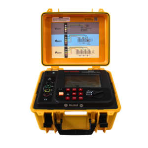
Click the picture to know more about Wrindu Earth Resistance Tester.
What Are the Three Electrodes Used in 3-Point Testing?
1. Test Electrode (X)
This is the target grounding system under detection, including transformer grounding grids, substation earth electrodes, and equipment grounding conductors. All test data is based on this electrode’s connection status and soil contact condition.
2. Current Electrode (C)
It is an auxiliary electrode that builds a complete current loop with the test electrode. The ground resistance tester injects stable AC test current through this electrode into the surrounding soil to form a measurable current path.
3. Potential Electrode (P)
This electrode is responsible for detecting the voltage drop between itself and the test electrode. The tester calculates final ground resistance by combining the measured voltage value and fixed test current.
How to Perform a 3-Point Ground Resistance Test Step by Step?
Step 1: Complete Pre-Test Preparation
Inspect the integrity of the grounding electrode and connection points, remove rust or dirt to ensure tight and clean contact. Disconnect parallel grounding paths if needed to avoid interference with test accuracy. Check the ground resistance tester and all cables for damage before testing.
Step 2: Arrange Auxiliary Electrodes Correctly
Place the current electrode (C) at a sufficient distance from the test electrode (X) to prevent overlapping soil resistance zones. Install the potential electrode (P) at about 62% of the straight-line distance between X and C, which is the optimal position for accurate voltage measurement.
Step 3: Connect Test Cables
Link the tester’s X/E terminal to the test grounding system, P terminal to the potential electrode, and C terminal to the current electrode. Double-check all connections to avoid loose wiring that causes unstable readings.
Step 4: Run Test and Collect Data
Turn on the tester to output stable AC test current. The instrument automatically measures voltage drop and calculates ground resistance based on the formula R=V/I. AC current is used to eliminate DC polarization errors in soil.
Step 5: Verify and Record Test Results
Confirm the reading is stable and repeatable. For high-voltage and key equipment systems, adjust the potential electrode position slightly for multiple tests to ensure data authenticity, then record the final valid resistance value.
What Are the Key Best Practices for Accurate 3-Point Testing?
First, avoid test sites near underground cables, transformers and high-power equipment to reduce electromagnetic interference. Second, strictly follow standard electrode spacing according to soil resistivity and electrode depth. Third, test in stable soil conditions; avoid testing immediately after extreme drought or heavy rain for standard data comparison.
FAQs
Q1: Why is 62% distance the standard for potential electrode placement?
A: The 62% position avoids the overlapping resistance zone of the current electrode and test electrode, ensuring the tester captures the true voltage drop of the grounding system and eliminates systematic errors.
Q2: Can 3-point testing be done without disconnecting grounding wires?
A: Traditional 3-point testing requires disconnecting parallel grounding paths for high accuracy. If non-disconnection testing is needed, choose the clamp-on testing method instead.
Q3: Is the 3-point method suitable for all grounding systems?
A: Yes, it is suitable for substations, industrial grounding grids, transformer grounding systems and large-scale renewable energy grounding projects, and is recognized as the most authoritative testing method.
Q4: What causes unstable readings in 3-point ground resistance tests?
A: Common reasons include poor electrode soil contact, loose cable connections, strong electromagnetic interference, and unstable soil moisture and temperature.
