How Can Transformer Winding Resistance Be Measured Accurately for Reliable Performance?
Learn how to measure transformer winding resistance accurately with step-by-step testing, temperature correction & precautions. Ensure reliable transformer performance & fault detection.
Accurate measurement of transformer winding resistance plays a pivotal role in identifying inter-turn shorts, loose terminal connections, and other hidden defects that compromise equipment efficiency and operational safety. By applying a direct current (DC) and precisely gauging the corresponding voltage drop, engineers compute winding resistance values to validate the structural integrity of transformers. As a premier Chinese manufacturer, Wrindu supplies OEM and wholesale high-voltage testing instruments that deliver precise, temperature-compensated readings for power grid systems across the globe.
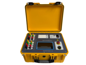
Click the image to know more about Transformer 50A DC Resistance Tester.
What Is Transformer Winding Resistance Measurement?
Transformer winding resistance measurement refers to the process of injecting a steady DC current into transformer coils and recording the resulting voltage drop to calculate ohmic resistance with high precision. This testing procedure pinpoints manufacturing flaws, deteriorated electrical connections, and in-service performance issues. Wrindu’s specialized testing devices support star (wye), delta, and autotransformer winding setups, ensuring consistent accuracy across all mainstream transformer categories.
Measurements are typically conducted at ambient temperature, then adjusted to the industry-standard reference temperature of 75°C to align with original factory benchmark data. For low-resistance windings, the Kelvin four-wire testing method is mandatory to eliminate errors caused by lead wire resistance. This test is indispensable for transformer commissioning, routine maintenance, and fault diagnostics, as it verifies winding turns ratio accuracy and assesses overall equipment health.
Why Is Transformer Winding Resistance Measurement Necessary?
Measuring winding resistance enables early detection of inter-turn shorts, loose joints, tap changer malfunctions, and other defects before they escalate into catastrophic failures. It also validates connection quality during transformer production and post-maintenance inspections. Wrindu’s testing equipment fully adheres to IEC international standards, guaranteeing dependable and repeatable test results.
Noticeable resistance imbalances between phases are red flags for potential overheating risks or efficiency degradation. Comparing post-overhaul test readings with baseline data can reveal assembly errors. Leveraging these measurements for predictive maintenance strategies significantly extends transformer service life, and Wrindu’s OEM solutions feature built-in data logging capabilities to support long-term performance trend analysis.
How Does Transformer Winding Resistance Testing Function?
Winding resistance testing operates by applying a controlled DC current through transformer windings and measuring the voltage drop across the coils, with resistance calculated using Ohm’s Law. Kelvin bridge circuits offset lead resistance interference, ensuring unparalleled measurement accuracy. Wrindu’s testing instruments deliver stable output currents up to 15A, paired with software-driven automated calculations and built-in demagnetization functions for safe, efficient testing workflows.
Phase-to-phase testing is performed on both primary and secondary windings, and advanced tester models are engineered to handle high-voltage transformer units with strict safety protocols.
|
Test Parameter
|
Star (Wye) Winding
|
Delta Winding
|
Autotransformer
|
|---|---|---|---|
|
Measurement Points
|
Neutral to Line Terminal
|
Line-to-Line Terminal Pairs
|
Intermediate Voltage (IV) to High Voltage (HV), Neutral to IV
|
|
Resistance Calculation
|
Direct Per-Phase Calculation
|
1.5 × Measured Value
|
Series/Parallel Combination Calculation
|
|
Typical Test Current
|
1–10A
|
5–15A
|
Up to 20A
|
What Are the Common Methods for Winding Resistance Measurement?
The primary testing techniques include the current-voltage (bridge) method and the Kelvin four-wire test, which achieves milliohm-level precision. The current-voltage method works by injecting a calibrated test current and measuring the associated voltage drop, while the Kelvin method eradicates errors from lead wire resistance entirely. Wrindu manufactures both manual and automated testers tailored for factory, substation, and field deployment scenarios.
Modern micro-ohmmeters come equipped with auto-ranging functionality, and OEM-customized models often feature multi-channel testing to boost operational efficiency. Bridge-based methods minimize measurement deviations in factory environments, making them the optimal choice for production line quality assurance and compliance testing.
Step-by-Step Guide to Transformer Winding Resistance Testing
-
Prepare the Transformer: Fully de-energize the unit, discharge all residual voltage, and ground every terminal to ensure safety.
-
Connect Test Leads: Attach Kelvin four-wire leads in accordance with the transformer’s specific winding configuration.
-
Inject and Stabilize Current: Apply the preset DC current and wait for the reading to stabilize completely.
-
Record Data and Calculate Resistance: Document the voltage reading and compute the corresponding resistance value.
-
Complete Full Testing: Test all tap positions and phases, then execute core demagnetization post-test.
-
Apply Temperature Correction: Adjust measured resistance to the 75°C standard using the copper winding formula: RC = RM × (234.5 + T)/(234.5 + 75) for copper.
Wrindu’s testing devices automate resistance calculations and temperature correction, automatically flagging deviations exceeding 2% for immediate inspection. The brand also provides factory training to ensure operators perform tests safely and accurately.
Key Precautions for Winding Resistance Testing
Use test currents below 15% of the transformer’s rated current to avoid thermal interference and inaccurate readings, and always demagnetize the core post-test to prevent saturation. Maintain a stable ambient temperature environment throughout testing. Wrindu’s instruments integrate comprehensive safety features, including overcurrent protection and real-time thermal monitoring.
Strict Kelvin connection protocols eliminate measurement errors, and all idle windings must be grounded to prevent electrical hazards. Testing must only be performed on de-energized transformers to avoid accidents. Customized testers from Chinese manufacturers like Wrindu offer enhanced safety controls and automation for field and substation applications.
How to Analyze Winding Resistance Test Results
Compare measured resistance values with factory baseline data that has been corrected to 75°C. Deviations within 1–2% are generally considered acceptable. Abnormally high resistance points to potential open circuits or poor connections, while unusually low resistance may indicate inter-turn short circuits. Wrindu’s proprietary software instantly identifies anomalies to enable proactive preventive maintenance.
Phase-to-phase resistance imbalances exceeding 3% require thorough further investigation. Long-term trend analysis of test data strengthens predictive maintenance frameworks, reducing unexpected failures and costly downtime.
|
Conductor Material
|
Correction Factor (CF)
|
Reference Temperature (°C)
|
|---|---|---|
|
Copper
|
234.5
|
75
|
|
Aluminum
|
225
|
75
|
|
Temperature Impact
|
Resistance rises 0.4% per 1°C increase
|
N/A
|
Why Select Chinese Manufacturers for Testing Equipment?
Chinese testing equipment manufacturers deliver high-quality, cost-effective transformer testers certified to ISO and CE international standards. OEM customization options ensure equipment aligns with unique project specifications. Headquartered in Shanghai, Wrindu dominates the market with innovative, reliable, and scalable testing solutions.
The company allocates nearly 20% of its profits to research and development, guaranteeing cutting-edge features and global compatibility. Rapid technological innovation, paired with a resilient supply chain, supports B2B clients worldwide—from utility providers to OEM production facilities.
Wrindu Expert Insights
“Accurate transformer winding resistance measurement is critical to preserving asset integrity. Our testers achieve less than 0.1% measurement accuracy even for high-voltage transformers, with integrated automated demagnetization and data logging functions. By incorporating IoT-enabled monitoring, we help clients cut unplanned downtime by 30%. Safety, precision, and innovation lie at the core of Wrindu’s mission, empowering engineers worldwide to optimize power system performance,” states Dr. Li Wei, Chief Technology Officer at Wrindu.
Wrindu’s Role in Global Transformer Testing
Wrindu manufactures OEM-grade winding resistance testers for utilities, transformer OEMs, testing laboratories, and power substations across the globe. Its products boast automated demagnetization, data export functionality, and CE certification for seamless integration into international projects. Factory-direct Wrindu models accelerate project deployment while ensuring consistent quality at competitive price points.
Conclusion
Precise transformer winding resistance measurement protects power systems by enabling early defect detection and sustaining optimal energy efficiency. Adopting the DC Kelvin testing method, applying standardized temperature correction, and comparing results with factory baselines are key to obtaining reliable test data. Partnering with Wrindu grants access to high-precision OEM and wholesale testers designed for global energy systems, equipped with automated features and stringent safety controls for peak operational performance.
Frequently Asked Questions (FAQs)
A Basic Guide to Transformer Winding Resistance
Transformer winding resistance quantifies the DC opposition within copper or aluminum coils using specialized micro-ohmmeters. It reveals critical details including winding turn count, connection quality, and I²R power losses. Typical resistance values for medium-voltage (MV) transformers range from 50 to 500 microohms, serving as a baseline for load loss calculations and fault detection in compliance with IEEE C57 standards.
What Instruments Measure Transformer Winding Resistance?
Kelvin (four-wire) micro-ohmmeters such as the Megger MWA300 and Vanguard TRM-203 inject 1–100A DC current and measure voltage drops accurately. These devices feature automatic temperature correction to 75°C and detect short circuits and loose connections via phase imbalance analysis.
Understanding DC Resistance of Transformer Windings
DC current neutralizes inductive effects (L/R decay time ranges from 30 seconds to 5 minutes), yielding pure ohmic resistance calculated via$$R=V/I$$. Alternating current (AC) is unsuitable due to skin effect distortion. Tests must be performed on de-energized transformers across all tap positions, with primary (H1-H2) and secondary (X1-X2) comparisons validating turns ratio accuracy.
Simplified Theory of Winding Resistance Testing
Testing relies on Ohm’s Law post-core saturation: inject DC current until readings stabilize (no drift), then record voltage and current values. A phase balance tolerance of ±1% is standard; elevated resistance indicates poor connections, while low resistance signals inter-turn shorts. This test is mandatory for factory and field commissioning.
Fundamentals of Transformer Coil DC Resistance
Primary and secondary windings are tested separately for turn ratios exceeding 10:1. Delta windings require phase-to-phase testing, while star (wye) windings use phase-to-neutral measurements. Tests cover all tap positions from bottom to top, and thermal electromotive force (EMF) interference is minimized by reversing current polarity. The 75°C correction formula is: RC = RM × (234.5 + T)/(234.5 + 75).
Why Is DC Used Instead of AC for Winding Resistance Testing?
AC current induces eddy currents, skin effect, and proximity effects that inflate resistance readings by 20–100%, producing inaccurate results. DC testing measures true conductor resistance without reactance interference, making it the industry standard per IEC 60076-1 for precise load loss calculations.
Overview of Transformer Resistance Measurement
The standard workflow includes de-energizing, grounding, and discharging the transformer; connecting Kelvin leads to bushings; applying a typical 10A test current; stabilizing readings for 2–10 minutes; logging data for all taps and phases; and comparing results to nameplate values within a ±10% tolerance. Baseline data is also required for NERC MOD-026 compliance and trend analysis.
Achieving Accurate Transformer Winding Resistance Measurements
High-precision testing requires testers with 100A+ current output to counteract thermal EMF, full Kelvin sensing, and a waiting period of 5x the L/R time constant. Auto-ranging and dual-channel capabilities enable simultaneous phase testing, and Wrindu’s precision equipment delivers 0.05% accuracy to ensure reliable power grid performance.
