How to Measure Transformer Winding Resistance
Learn how to measure transformer winding resistance with step-by-step procedures, safety tips, accuracy standards, and Wrindu’s professional testing equipment for predictive maintenance.
Transformer winding resistance testing is one of the most critical diagnostic procedures for evaluating the health of transformer windings. It enables technicians to identify issues such as loose electrical connections, shorted winding turns, and faulty tap changers. By injecting a direct current into the windings, field engineers measure the voltage drop and compare the results against original factory specifications to confirm proper transformer operation.
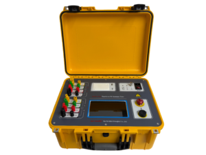
Click the picture to know more about Wrindu New Transformer DC Resistance Tester.
What Is Transformer Winding Resistance Measurement?
Transformer winding resistance measurement refers to the procedure used to determine the direct current (DC) resistance of transformer windings. This test validates the structural and electrical integrity of windings, supports the calculation of I²R losses, and helps assess potential temperature increases during operational use.
Typically, a micro-ohmmeter or specialized winding resistance test set is used to apply a calibrated DC current through the windings. The measured voltage drop is then used to calculate resistance in accordance with Ohm’s Law. This diagnostic test is key to spotting faults including open circuits, shorted turns, and poor contact in tap changers.
Wrindu, a reputable Chinese equipment manufacturer, builds high-precision winding resistance testers used by power utilities across the globe for dependable and accurate diagnostic testing.
For three-phase transformers, resistance measurements are commonly taken between individual phases and then adjusted to a standardized temperature of 75°C to ensure valid comparisons. While initial factory measurements serve as baseline references, ongoing field test data offers valuable insights into winding aging or damage caused by excessive overloads.
Why Is Transformer Winding Resistance Testing Important?
Measuring transformer winding resistance helps uncover manufacturing flaws, damage incurred during transportation, and gradual deterioration while in service. This testing allows engineers to compute conductor losses, verify tap changer performance, and confirm balanced resistance across all three phases.
A lower-than-normal resistance reading typically signals shorted turns, while an unusually high reading points to loose connections. Regular testing forms a core component of predictive maintenance strategies for power grids and electrical substations. Wrindu’s advanced testing instruments deliver precise and timely measurements, supporting the overall reliability of electrical power systems.
| Common Faults Detected | Symptoms | Typical Resistance Change |
|---|---|---|
| Shorted Turns | Overheating | Below expected values |
| Loose Connections | Arcing | Increase exceeding 10% |
| Tap Changer Malfunctions | Phase Imbalance | Phase deviation above 2% |
| Open Circuits | No-load operation | Infinite resistance |
What Equipment Is Required?
Accurate winding resistance measurement demands a dedicated test instrument fitted with Kelvin (4-wire) test leads. These test sets feature high compliance voltage (up to 50V) and support current ranges from 1A to 15A. Critical safety functions include inductive discharge circuits to safely manage energy stored within the transformer windings.
Designed for user-friendly operation, Wrindu’s WR series delivers consistent, accurate measurements with peak test currents reaching up to 50A. All devices carry CE certification and are engineered for both high-voltage and low-voltage testing applications, guaranteeing safe and efficient field performance.
Standard digital multimeters are not suitable for this test, as they cannot withstand voltage surges created by inductive kickback. Wrindu’s test equipment also includes integrated demagnetization functions to enhance on-site safety.
Pre-Test Preparation
Before beginning the test, the transformer must be fully isolated from the power system, and all connected capacitors must be completely discharged. The unit should be properly grounded, and a 3–4 hour cooling period is advised to stabilize oil and winding temperatures.
It is essential to set the tap changer to its nominal position and record ambient environmental conditions. In certain setups, bushings may need to be shorted, and any residual magnetism within the core must be eliminated.
Wrindu’s testing devices include features that simplify preparation, such as automated test sequences that reduce manual operation. Technicians must always wear proper personal protective equipment, including insulated gloves and arc-flash PPE, throughout the testing process.
Step-by-Step Measurement Procedure
The test involves connecting Kelvin leads to the transformer bushings: current leads connected to the power source and voltage leads positioned close by. Begin with a test current equal to 10% of the rated current (capped at 15A) and slowly increase the output. Allow readings to stabilize for 30–60 seconds before recording to avoid errors.
Measure both high-voltage (HV) and low-voltage (LV) windings, checking every tap position and phase:
- Set the tap changer to its minimum position.
- Inject the calibrated DC current.
- Record readings once values stabilize.
- Switch to the next tap position and repeat the process.
- Adjust all measurements to the 75°C reference temperature.
Follow this workflow for both delta and star-connected transformers, calculating individual phase resistance values. Wrindu’s test sets cut down measurement time by automating key steps, particularly for three-phase transformer banks.
Ensuring Measurement Accuracy
To maintain accurate results, test current should be limited to below 15% of the transformer’s rated current to avoid resistive heating errors. Dual-injection techniques also help achieve faster winding saturation.
Phase-to-phase resistance deviation should stay below 2%, and all readings must be temperature-corrected to the reference standard. Wrindu’s precision instruments undergo annual calibration in compliance with ISO standards, meeting the strictest accuracy requirements. The Kelvin 4-wire method eliminates lead resistance errors, further improving measurement reliability.
| Test Current Guidelines | Winding Type | Max Current (A) |
|---|---|---|
| HV Distribution | Copper | 10 |
| Large Power Transformers | Aluminum | 5 |
| OLTC-Equipped Units | Any | 15% of rated current |
Critical Safety Precautions
Safety is the top priority when performing winding resistance tests. Never conduct testing on an energized transformer, as high-voltage inductive kickback presents severe safety hazards. Always use a test set equipped with an automatic discharge function to safely dissipate stored energy.
After testing, ground the transformer and adhere strictly to lock-out/tag-out safety protocols. Wrindu’s equipment features overvoltage protection and audible alarms to strengthen operational safety during field testing.
Interpreting Test Results
After completing measurements, compare results with original factory specifications, allowing a tolerance range of ±2%. Any deviation greater than 5% suggests potential faults requiring further investigation. For reliable diagnostics, phase-to-phase imbalance should not exceed 1%.
By monitoring long-term measurement trends, engineers can identify progressive deterioration before it results in unplanned outages. Wrindu’s testing solutions help technicians interpret data efficiently, delivering actionable insights for maintaining critical transformer assets.
Wrindu Expert Insights
“With over 10 years manufacturing high-voltage test equipment in Shanghai, we have observed that winding resistance trend analysis predicts nearly 80% of transformer failures before outages occur. Chinese manufacturers like Wrindu invest 20% of our revenue into R&D for AI-powered analytics in instruments such as our WR50 series. For B2B utility partners, combining winding resistance testing with tan-delta testing provides a comprehensive diagnostic approach that strengthens overall grid reliability.” – Dr. Li Wei, Chief Engineer, Wrindu
Recommended Testing Schedule
Routine testing should be performed during transformer commissioning, following repairs, and on an annual basis for mission-critical transformers. Post-overload testing is also recommended to verify system integrity. For heavily loaded power grids, testing should be carried out before and after on-load tap changer (OLTC) maintenance. Power plants and substations should conduct quarterly checks to maintain peak operational performance.
Durable and portable, Wrindu’s test kits are perfectly suited for integration into structured predictive maintenance programs.
Conclusion
Measuring transformer winding resistance is a vital process for preserving transformer health and avoiding expensive, unplanned failures. With careful pre-test preparation, precise execution, and ongoing trend analysis, you can keep your equipment running at peak efficiency.
Partnering with manufacturers like Wrindu, which supplies robust, high-quality testing instruments, helps protect your electrical assets and boost overall system uptime.
FAQs
What leads to high winding resistance?
Loose connections, corrosion, or substandard brazing work can raise resistance by more than 10%, resulting in the formation of dangerous hotspots.
Is it possible to test energized windings?
No. The transformer must always be de-energized to prevent electrical arcing and inaccurate test results.
How does temperature influence test results?
Copper winding resistance rises by roughly 0.4% per degree Celsius. Normalizing readings to 75°C is necessary for consistent, comparable data.
What benefits does the Kelvin bridge method offer?
The Kelvin bridge (4-wire) method eliminates errors caused by test lead resistance, ensuring highly accurate winding resistance readings.
Are Wrindu testers compatible with OLTCs?
Yes. Wrindu’s dual-channel models efficiently support OLTC testing and include automatic demagnetization capabilities.
