Relay Commissioning Checklist for Substations
Complete relay commissioning checklist for substations, covering documentation review, injection testing, CT polarity checks, and trip verification.
Relay commissioning is one of the most critical stages in any power system project. Before a substation is energized, every protection relay must be thoroughly verified to ensure it operates exactly as designed. A structured commissioning workflow reduces risk, prevents equipment damage, and guarantees long-term system reliability.
Skipping steps during commissioning can result in misoperations, nuisance tripping, equipment failure, or even large-scale outages. A disciplined testing process ensures that protection schemes function correctly under real operating conditions.
Why Relay Commissioning Is So Important?
Protective relays are responsible for detecting abnormal conditions such as:
-
Overcurrent
-
Short circuits
-
Earth faults
-
Differential imbalance
-
Over/undervoltage
If a relay fails to trip when required, equipment such as transformers, circuit breakers, and cables can suffer severe damage. If it trips unnecessarily, it may cause production losses or system instability.
Commissioning testing ensures:
-
Correct settings implementation
-
Proper wiring connections
-
CT and PT polarity accuracy
-
Trip circuit reliability
-
Coordination with upstream and downstream protection
Complete Relay Commissioning Workflow
A professional commissioning procedure follows a logical sequence. Each step builds on the previous one to eliminate risk before energization.
1️⃣ Documentation Review
Before any physical testing begins, all documentation must be carefully reviewed.
Key Items to Verify:
-
Protection setting sheets
-
Single-line diagrams
-
Wiring schematics
-
CT (Current Transformer) ratios and polarity
-
PT (Potential Transformer) specifications
-
Relay configuration files
Why It Matters
Many commissioning failures are caused by incorrect settings rather than hardware issues. Comparing relay configuration parameters against approved protection studies ensures consistency with system design.
2️⃣ Visual and Mechanical Inspection
A thorough visual inspection helps detect installation errors before electrical testing begins.
Inspection Checklist:
-
Tighten all terminals
-
Confirm correct wire numbering
-
Inspect grounding connections
-
Check panel labeling
-
Verify no foreign objects remain inside the panel
-
Ensure proper cable routing
For electromechanical relays, moving parts should be checked for smooth operation.
Common Issues Found
-
Loose CT secondary wiring
-
Incorrect polarity connections
-
Missing grounding straps
-
Incorrect terminal labeling
Early correction prevents unsafe test conditions later.
3️⃣ Insulation Resistance Test
Before energizing any circuits, insulation resistance must be verified.
Purpose:
-
Detect moisture ingress
-
Identify insulation damage
-
Prevent short circuits
A megohmmeter is typically used to measure resistance between:
-
Phase-to-ground
-
Phase-to-phase
-
Control circuit-to-ground
Low insulation values may indicate wiring damage or contamination.
4️⃣ Secondary Injection Test
Secondary injection testing verifies relay logic and performance without energizing the primary system.
What It Confirms:
-
Pickup current accuracy
-
Trip timing
-
Protection curve behavior
-
Alarm outputs
-
Communication signals (for digital relays)
Advantages:
-
Safe and controlled environment
-
High measurement accuracy
-
Suitable for complex protection schemes
This step ensures the relay operates according to its configuration settings.
5️⃣ Primary Injection Test
What It Covers:
-
CT ratio verification
-
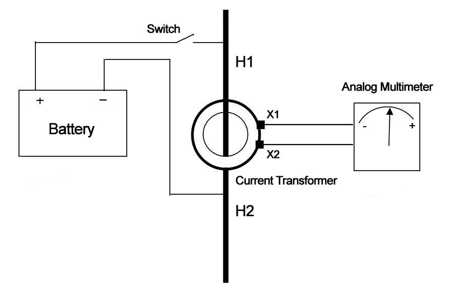
CT polarity confirmation
-
Wiring integrity
-
Relay trip logic
-
Circuit breaker operation
Why It Is Critical
Secondary injection tests the relay only. Primary injection confirms that the entire protection system works under real electrical conditions.
This step is especially important for:
-
New substations
-
System upgrades
-
CT replacements
-
Protection scheme modifications
6️⃣ Breaker Trip Verification
A relay trip signal must result in proper mechanical operation of the circuit breaker.
Verification Includes:
-
Trip coil energization
-
Breaker opening time
-
Mechanical latch release
-
Indication signals
Failure in the trip circuit can render the entire protection system ineffective.
Additional Advanced Commissioning Checks
For modern digital substations, commissioning may also include:
🔹 Logic Scheme Verification
Testing interlocking logic and automation sequences.
🔹 SCADA Communication Testing
Confirming data transmission to control centers.
🔹 Event Recorder Verification
Ensuring disturbance recording functions correctly.
🔹 Redundancy Testing
Testing backup protection schemes.
Common Commissioning Errors to Avoid
-
Skipping CT polarity testing
-
Failing to verify trip circuits under load
-
Ignoring manufacturer timing tolerances
-
Not documenting test results
-
Testing without proper safety isolation
A disciplined process reduces the likelihood of post-energization troubleshooting.
Why Commissioning Testing Matters?
Proper commissioning delivers several critical benefits:
✅ Confirms System Integrity
Ensures every component functions as a coordinated protection system.
✅ Prevents Startup Failures
Identifies errors before energization.
✅ Verifies Protection Coordination
Ensures selective fault clearing.
✅ Reduces Post-Energization Troubleshooting
Minimizes costly rework and downtime.
✅ Supports Regulatory Compliance
Provides documented evidence for safety audits.
