Step-by-Step Transformer Ratio Testing Guide | Field & Factory Procedures
Follow this step-by-step transformer ratio testing guide for field & factory use, covering prep, wiring, OLTC testing, data logging and IEC/IEEE compliance.
Transformer ratio testing is non-negotiable for verifying performance, catching hidden faults, and meeting global IEC 60076-1 and IEEE C57.12.90 standards. Whether you’re conducting field ratio testing for routine maintenance or factory transformer testing for final FAT (Factory Acceptance Testing), following a consistent, step-by-step process ensures accurate readings and compliance. This guide walks you through every stage, highlights key differences between field and factory workflows, and shares critical safety and error-avoidance tips.
Safety First: Always de-energize, lockout/tagout (LOTO) the transformer, and verify zero voltage before starting any testing. Never work on live equipment.
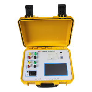
Click the image to know more about Transformer Turns Ratio Tester.
Pre-Test Preparation (Critical for Accurate Results)
Skipping prep work is the top cause of faulty readings and failed tests. Take these steps to set yourself up for success:
-
Gather Tools & Equipment: Grab a calibrated portable transformer ratio tester, insulated test leads, grounding wire, nameplate data sheet, and a logbook/digital recorder for data.
-
Inspect the Transformer: Check for loose terminals, damaged windings, oil leaks (for liquid-immersed units), or debris that could interfere with connections.
-
Demagnetize the Core: Residual magnetism skews readings—use your tester’s demagnetization function or a dedicated demagnetizer to clear the core before testing.
-
Record Nameplate Specs: Note the rated turns ratio, voltage ratings, tap positions, and vector group (e.g., Dyn11) for quick reference during testing.
Step-by-Step Transformer Ratio Testing Process
Step 1: Proper Wiring & Connection
Correct wiring prevents polarity errors and unsafe conditions. Match your tester’s labeled leads to the transformer terminals:
-
HV Side: Connect H1, H2, H3 (three-phase) or H leads (single-phase) to the high-voltage winding terminals
-
LV Side: Connect X1, X2, X3 (three-phase) or X leads (single-phase) to the low-voltage winding terminals
-
Ground Securely: Attach the tester’s ground clip to a reliable earth ground to reduce electrical interference
Double-check all clamps for tight, clean connections—loose leads cause erratic readings.
Step 2: Configure Test Parameters
Set up your tester to align with IEC & IEEE standards:
-
Input the transformer’s nameplate ratio and rated frequency (50/60 Hz)
-
Set test voltage to 5–10% of rated HV (safe for field use; factory testing may use slightly higher low voltage)
-
Enable tolerance alert (set to ±0.5%, the mandatory limit for compliance)
Step 3: Perform Ratio Testing (Including OLTC Testing)
Start with the main tap position, then testevery tap position sequentially for transformers with on-load tap changers (OLTC) or off-circuit tap changers:
-
Initiate the test on your tester— it will apply voltage to the HV winding and measure induced LV voltage
-
Wait for the tester to calculate the measured ratio and deviation percentage
-
For OLTC units, run the automated tap test function to cycle through all positions without manual reset
Step 4: Record Data & Judge Results
Log every reading, including tap position, measured ratio, deviation, and phase angle/polarity (per IEEE requirements). Mark a result as PASS if deviation stays within ±0.5%; mark as FAIL if it exceeds this limit.
Step 5: Post-Test Wrap-Up
-
Power off the tester and disconnect all leads in reverse order (LV first, then HV)
-
Re-demagnetize the transformer core if needed
-
Store test equipment properly and file digital/physical test reports for compliance records
Field vs. Factory Testing: Key Differences
|
Aspect
|
Field Ratio Testing
|
Factory Transformer Testing
|
|---|---|---|
|
Environment
|
Outdoor substations, remote sites, variable conditions
|
Controlled lab, clean power, stable temperature
|
|
Test Voltage
|
Lower (5–10% rated HV) for safety
|
Controlled low voltage, calibrated lab-grade power
|
|
Focus
|
Quick maintenance, fault detection, compliance checks
|
Full FAT, detailed reporting, vector group verification
|
|
Equipment
|
Portable, battery-powered, rugged testers
|
Bench-top & portable units, automated data logging
|
Common Mistakes & How to Avoid Them
-
Polarity Reversal: Double-check lead labels (H to HV, X to LV) to prevent false ratio readings
-
Skipping Demagnetization: Always demagnetize to eliminate residual magnetism errors
-
Missing Tap Positions: Test every OLTC tap—partial testing misses hidden tap changer faults
-
Loose Connections: Clean terminals and tighten clamps to avoid unstable voltage readings
How Wrindu Testers Stand Out for Step-by-Step Ratio Testing
Wrindu’s portable transformer ratio test kits streamline the entire testing process, making field and factory work faster, safer, and fully compliant with IEC 60076-1 and IEEE C57.12.90 standards. Here’s what sets them apart:
-
One-Touch Automated Testing: Preloaded IEC/IEEE parameters and auto-OLTC tap cycling eliminate manual setup errors
-
0.03% Ultra-High Accuracy: Far exceeds the ±0.5% tolerance, catching tiny deviations before they become failures
-
Built-In Demagnetization: No extra tools needed—demagnetize and test with one device
-
Rugged & Portable Design: Battery-powered, shock-resistant casing ideal for remote field sites
-
Instant Data Logging & Export: Auto-saves test reports (PDF/CSV) for FAT and maintenance records
-
Anti-Interference Technology: Delivers stable readings in noisy substation environments
FAQs: Transformer Ratio Testing (Long-Tail Q&A)
Q: How long does a full transformer ratio test take with OLTC?
A: With a Wrindu automated tester, a full OLTC ratio test (10–20 taps) takes 5–10 minutes. Manual testing can take 30+ minutes, depending on tap count.
Q: Can I do ratio testing without demagnetizing the transformer?
A: Skipping demagnetization often causes ratio deviations of 1% or more, leading to false failures. Always demagnetize to meet IEC/IEEE accuracy requirements.
Q: What test voltage is best for field ratio testing per IEC standards?
A: IEC 60076-1 recommends 5–10% of the transformer’s rated HV voltage for safe, accurate field testing—this is the default setting on Wrindu portable testers.
Q: Why do I need to test every tap position for OLTC transformers?
A: IEEE C57.12.90 requires full tap testing to detect worn contacts, misalignment, or winding faults that only appear at specific tap positions. Partial testing risks missing critical issues.
Q: What’s the difference between a pass and fail in ratio testing?
A: A reading with ≤±0.5% deviation from nameplate ratio is a PASS (compliant with IEC/IEEE). A deviation over ±0.5% is a FAIL, indicating winding damage, tap changer issues, or polarity errors.
Q: Can I use the same ratio tester for field and factory testing?
A: Yes—Wrindu’s portable testers are designed for both environments, with rugged casing for field use and lab-grade accuracy for factory FAT testing.
