Understanding CT Polarity Testing in Substations
Learn how CT polarity testing works in substations, why it prevents relay misoperation, and how IEC 61869 and IEEE C57.13 guide proper verification.

Introduction
CT polarity testing verifies the correct directional relationship between the primary and secondary windings of a current transformer (CT).
In substations, engineers rely on accurate polarity to ensure protection relays, metering systems, and differential schemes operate correctly. If polarity is wrong, protection systems may trip unnecessarily—or fail to trip during a fault.
This simple test plays a critical role in substation commissioning and maintenance.
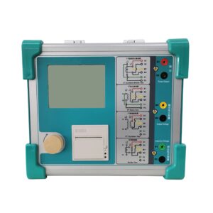
Click the iamge to know more about CT and PT Analyzer.
What Is CT Polarity?
Polarity defines how current enters and exits a current transformer.
Most CTs include terminal markings such as:
-
P1 / P2 – Primary terminals
-
S1 / S2 – Secondary terminals
When current enters P1, it should leave S1 at the same instantaneous direction. This relationship ensures that protection relays receive properly phased signals.
Incorrect wiring reverses this relationship and disrupts system coordination.
Why Is CT Polarity Testing Important in Substations?
1. Protects Relay Coordination
Protection schemes such as differential protection compare current direction. Wrong polarity causes false differential current, leading to unnecessary trips.
2. Ensures Accurate Metering
Energy meters rely on correct current flow direction. Reverse polarity produces inaccurate readings.
3. Prevents Commissioning Errors
Installation teams may accidentally reverse secondary wiring. A quick polarity check confirms proper connections before energizing the system.
4. Maintains System Stability
In high-voltage substations, even a small wiring mistake can trigger large-scale outages. Polarity verification reduces that risk.
How Do Engineers Perform a CT Polarity Test?
Engineers typically follow these steps:
-
Connect the CT analyzer or polarity test device to the secondary terminals.
-
Inject a low DC or AC signal into the primary winding.
-
Observe the secondary output direction.
-
Confirm whether the output matches expected polarity markings.
Modern CT analyzers perform this test automatically and display:
-
Polarity status (Correct / Reverse)
-
Phase relationship
-
Test waveform
Portable digital testers simplify field testing and improve accuracy.
Common Methods Used in CT Polarity Testing
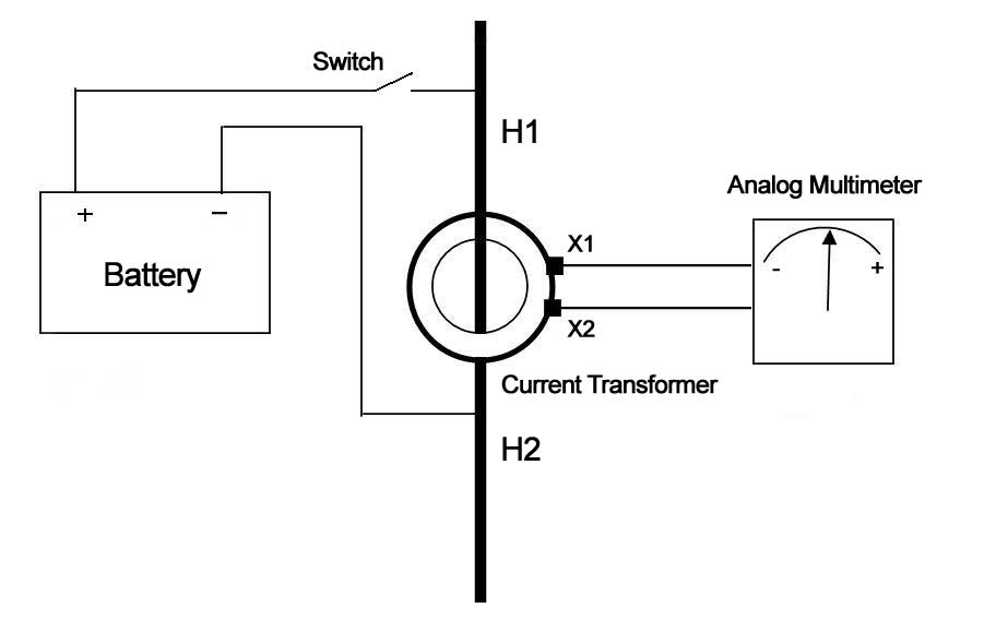
DC Kick Test
Engineers apply a small DC voltage to the primary and observe the needle movement of an analog meter connected to the secondary. The direction of movement indicates polarity.
AC Injection Test
A low AC current flows through the primary. Engineers compare phase angles between primary and secondary signals.
Automatic Analyzer Test
Digital CT analyzers determine polarity electronically and provide instant pass/fail results.
When Should You Perform CT Polarity Testing?
Engineers should perform polarity testing:
-
During new substation commissioning
-
After CT replacement
-
After wiring modifications
-
During relay upgrades
-
After maintenance work
Testing before energization prevents costly relay misoperation.
Which Standards Cover CT Polarity Testing?
Industry standards define CT performance and installation practices:
-
IEC 61869 – Specifies instrument transformer requirements and markings.
-
IEEE C57.13 – Defines CT polarity and performance standards in North America.
Compliance ensures safe and standardized installation across global substations.
What Problems Occur If Polarity Is Wrong?
Incorrect CT polarity can cause:
-
False differential relay trips
-
Protection relay failure during faults
-
Reverse power indication
-
Incorrect load measurement
-
System instability
In transformer differential protection, reversed polarity may cause immediate relay operation once energized.
How CT Polarity Affects Differential Protection
Differential protection compares current entering and leaving a transformer or busbar.
Correct polarity ensures:
Incoming current = Outgoing current (normal condition)
If polarity reverses on one CT, the relay detects artificial imbalance and trips immediately.
That is why engineers treat polarity testing as mandatory before energizing any differential scheme.
Tools Used for CT Polarity Testing
Modern substations use multi-function CT analyzers that combine:
-
Ratio testing
-
Polarity verification
-
Burden measurement
-
Magnetization curve testing
Integrated devices reduce setup time and improve commissioning efficiency.
Best Practices for Substation Engineers
-
Always verify terminal markings before wiring
-
Label secondary cables clearly
-
Perform polarity tests before connecting relays
-
Document results for audit and compliance
-
Repeat testing after maintenance work
Clear documentation helps prevent future troubleshooting confusion.
Wrindu Expert Review
CT polarity testing ensures correct directional current flow between primary and secondary windings. In substations, this simple verification protects relay coordination, prevents false trips, and guarantees accurate metering.
Engineers should treat CT polarity testing as a mandatory step during commissioning and maintenance. A few minutes of testing can prevent major protection failures and costly downtime.
