What Is the 4-Wire Kelvin Method and Core Working Principles
Master the 4-wire Kelvin method for ultra-precise low resistance measurement. Learn how it works, step-by-step usage, benefits, applications & why it beats 2-wire testing.
What Is the 4-Wire Kelvin Method & Core Working Principles
In the field of precision electrical testing, the 4-Wire Kelvin Method (also widely known as Kelvin connection or four-terminal sensing) stands as the gold-standard technique for measuring low resistance values with unparalleled accuracy. Designed to eliminate the inherent errors of traditional resistance testing, this method is indispensable for industrial technicians, OEM quality control teams, and electrical engineers working with milliohm and microohm-level components, from power cables and transformer windings to PCB traces and EV battery connections.
Unlike basic resistance testing approaches, the 4-Wire Kelvin Method targets and eradicates two major sources of measurement error: test lead resistance and contact resistance. For anyone handling high-precision electrical diagnostics, understanding this method’s definition and core principles is the first step to reliable, compliant testing results—before diving into hands-on operation, it’s critical to grasp how this technique achieves industry-leading accuracy, and how it stacks up against older methods via 2-wire vs 4-wire resistance measurement comparisons.
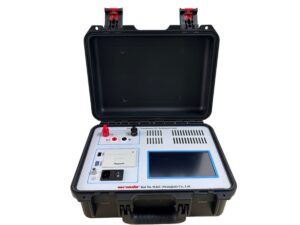
Click the image to know more about Wrindu DC Resistance Tester.
Formal Definition of the 4-Wire Kelvin Method
The 4-Wire Kelvin Method is a non-invasive, high-precision resistance measurement technique that uses four separate electrical leads to isolate current injection and voltage sensing, completely removing external resistance interference from the final measurement reading. It operates on the foundation of Kelvin connection basics, a specialized circuit design that separates the paths of current flow and voltage detection—this core separation is what makes it vastly more accurate than 2-wire testing for low-resistance applications.
This method is specifically engineered for resistance values below 1Ω, where even tiny amounts of lead or contact resistance (typically 0.1Ω to 0.5Ω) can skew 2-wire test results beyond usability. By implementing the 4-wire Kelvin structure, technicians can capture precise resistance readings down to the microohm level, making it a staple for quality assurance, equipment maintenance, and regulatory compliance across power utilities, electronics manufacturing, automotive, and heavy industrial sectors.
Core Circuit Principles of the 4-Wire Kelvin Method
The functionality of the 4-Wire Kelvin Method revolves around a dual-circuit design, with four distinct test leads split into two dedicated pairs, each serving a unique and non-overlapping purpose. This dual-pair setup is the heart of the technique’s accuracy, and it aligns directly with the foundational rules of Kelvin connection basics:
1. Force Leads (Current-Carrying Leads)
The first pair of leads, referred to as force leads, is responsible for delivering a stable, calibrated test current through the component or material being measured. These leads carry the full test current, but they do not participate in the voltage measurement process. This means any resistance present in these force leads—whether from wire material, length, or connection points—has no impact on the final resistance calculation, eliminating a major source of error.
2. Sense Leads (Voltage-Sensing Leads)
The second pair, known as sense leads, is connected directly across the target component to measure the voltage drop created by the test current from the force leads. Critical to this design: high-impedance measurement tools (like Kelvin-enabled multimeters or micro-ohmmeters) draw almost no current through the sense leads, so lead resistance and contact resistance at the sensing points are negligible and do not affect the voltage reading. This pure voltage measurement is the key to accurate low-resistance testing.
Key Circuit Rule
The sense leads are always connected inside the force leads on the component under test. This placement ensures the voltage reading reflects only the resistance of the target component, not the resistance of the test leads or contact points—this is the defining characteristic of the Kelvin connection that sets it apart from standard 2-wire setups.
Calculation Logic: Ohm’s Law in the 4-Wire Kelvin Method
The 4-Wire Kelvin Method relies on fundamental Ohm’s Law for its final resistance calculation, with the isolated voltage and current values ensuring total accuracy. Unlike 2-wire testing, which combines component resistance with lead/contact resistance in the final reading, this technique uses only the pure voltage drop across the component and the known test current to compute true resistance.
The core formula applied in the 4-Wire Kelvin Method is:
$$R = \frac{V}{I}$$
-
R: True resistance of the target component (measured in ohms Ω, milliohms mΩ, or microohms μΩ)
-
V: Accurate voltage drop measured by the sense leads (volts V)
-
I: Constant, calibrated test current supplied by the force leads (amps A)
This calculation excludes all external resistance variables, delivering a measurement that is unaffected by lead length, probe quality, or minor contact inconsistencies—something that standard 2-wire testing cannot achieve. To fully grasp this advantage, a deep dive into 2-wire vs 4-wire resistance measurement highlights the stark differences in accuracy and application scope.
Why These Core Principles Matter for Industrial Testing
For industrial and OEM applications, the principles behind the 4-Wire Kelvin Method solve critical pain points that lead to faulty components, equipment failures, and safety risks. Loose connections, corroded terminals, and subpar components often exhibit only minor low-resistance anomalies that 2-wire tests miss, but the 4-wire Kelvin’s precision detects these issues early.
By grounding testing in the core circuit and calculation principles of the Kelvin method, teams can reduce unplanned downtime, meet strict ISO/IEC industrial standards, and ensure the reliability of critical systems—from power grid substations to electric vehicle battery packs. Mastering these fundamentals also simplifies troubleshooting and reduces measurement errors, making it a non-negotiable skill for precision-focused electrical testing.
Internal Link Navigation
