What Is the Earthing Resistance Value and Why Is It Important for Safety?
Learn what earthing resistance value means, why it matters for electrical safety, and the recommended ohm levels for substations, industry, and homes.
- BYwrindu
- On
- InTechnical FAQs
Earthing resistance value indicates the level of resistance between a grounding electrode and the surrounding soil. It determines how effectively fault current can flow into the earth during abnormal conditions. The acceptable value depends on the application. Power stations and substations typically require values below 1 ohm, industrial systems usually aim for less than 2 ohms, and residential installations may allow values up to 5 ohms. Reliable testing equipment helps ensure these requirements are consistently achieved and maintained.
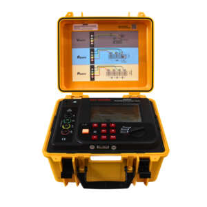
Click the picture to know more about Wrindu Earth Resistance Tester.
What Is Earthing Resistance?
Earthing resistance describes the opposition encountered by fault current as it travels from a grounding electrode into the earth. This parameter is essential for electrical protection systems. A lower resistance allows fault current to dissipate quickly, reducing the risk of electric shock and preventing damage to electrical assets.
Several factors influence earthing resistance:
-
Soil resistivity: Clay, sand, and rock all have different electrical properties. Wet soil generally lowers resistance, while dry or rocky soil increases it.
-
Electrode material and configuration: Copper and galvanized steel provide strong conductivity. The size and geometry of the electrode also affect performance.
-
Installation depth: Deeper electrode placement usually improves grounding performance and reduces resistance.
Accurate measurement ensures grounding systems operate safely and effectively under fault conditions.
Why Is Earthing Resistance Important?
Proper earthing resistance is critical for electrical system safety. When faults occur, grounding prevents dangerous voltage buildup on equipment enclosures and structures. If resistance is too high, hazardous touch and step voltages may develop, increasing the risk of serious injury.
Maintaining correct earthing resistance helps:
-
Reduce electrical hazards
-
Protect personnel from shock
-
Prevent equipment damage
-
Minimize downtime in industrial and power systems
Compliance with international safety frameworks such as IEEE and IEC guidelines depends heavily on effective grounding performance.
What Are Acceptable Earthing Resistance Values?
Acceptable values vary by installation type:
-
Power stations and substations: Less than 1 ohm
-
Industrial installations: Less than 2 ohms
-
Residential buildings: Up to 5 ohms
These limits ensure safe fault current dissipation and reliable operation of protection devices. Keeping resistance within these ranges significantly lowers the risk of electrical accidents.
How Is Earthing Resistance Measured?
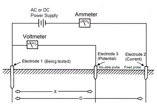
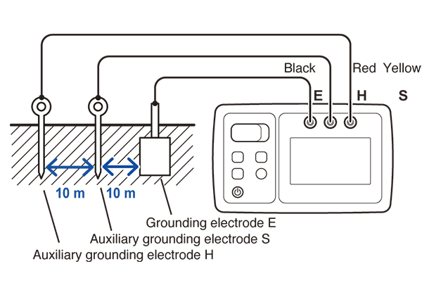
To obtain accurate readings:
-
Test stakes should be positioned 50–100 meters apart when possible.
-
Probes should be inserted in uniform soil conditions.
-
Multiple measurements should be taken to confirm consistency.
The Wenner four-probe method is commonly used to determine soil resistivity, which assists in grounding system design.
What Factors Affect Earthing Resistance?
Several environmental and design factors influence earthing resistance:
-
Soil resistivity: High-resistivity soil (dry sand or rock) increases resistance.
-
Moisture and temperature: Wet soil reduces resistance, while dry or frozen soil increases it.
-
Electrode size and depth: Larger surface area and deeper placement lower resistance values.
Below is a general comparison of soil types:
| Soil Type | Resistivity (Ohm-m) | Mitigation Strategy |
|---|---|---|
| Clay / Wet soil | 20–100 | Standard grounding rods |
| Sand / Dry soil | 100–1000 | Chemical or conductive backfill |
| Rock | >1000 | Deep wells or grounding grids |
Understanding these variables allows engineers to design more effective grounding systems.
How Can High Earthing Resistance Be Reduced?
If earthing resistance exceeds recommended limits, several corrective actions can be applied:
-
Install multiple parallel electrodes to increase surface contact.
-
Drive vertical electrodes deeper into lower-resistivity layers.
-
Use grounding grids to distribute fault current more evenly.
-
Apply conductive backfill materials such as bentonite or grounding enhancement compounds.
These approaches improve current dissipation and enhance overall system safety.
What Role Does Soil Resistivity Play?
Soil resistivity directly impacts earthing resistance. Low-resistivity soils allow easier current flow, producing lower resistance values. High-resistivity soils restrict current flow, requiring enhanced grounding solutions.
The Wenner four-probe method is commonly used to measure soil resistivity before designing a grounding system. Accurate soil profiling helps ensure the final installation meets safety and regulatory standards.
Wrindu Expert Insight
“Precise earthing resistance measurement is becoming increasingly important, especially in areas with high soil resistivity. Advanced testing technology allows engineers to achieve resistance values below 1 ohm even in challenging environments. For substations and power plants, accurate real-time data ensures compliance, reliability, and long-term operational safety.”
— Dr. Li Wei, Chief Engineer
Which Standards Govern Earthing Resistance?
Earthing resistance practices are guided by recognized international standards, including:
-
Institute of Electrical and Electronics Engineers (IEEE 80, IEEE 81)
-
International Electrotechnical Commission (IEC 60364, IEC 62305)
-
GB 50057 (Chinese grounding standard)
These documents define testing procedures, grid design principles, and acceptable safety limits.
How to Select Reliable Testing Equipment?
When choosing earthing resistance testing instruments, consider:
-
Certification: ISO and CE compliance
-
Accuracy: Preferably within ±2%
-
Durability: Rugged, weather-resistant housing (e.g., IP67)
-
Portability: Lightweight for field testing
-
Customization: OEM options if required
High-quality testing equipment ensures accurate data collection and regulatory compliance.
Maintaining proper earthing resistance is essential for electrical safety, equipment protection, and regulatory compliance. Power stations typically require values below 1 ohm, industrial systems below 2 ohms, and residential systems up to 5 ohms. Soil conditions, electrode design, and environmental factors all influence final resistance values.
Routine testing, careful system design, and adherence to international standards are key to ensuring a safe and stable electrical infrastructure.
Frequently Asked Questions
What Defines Earthing Resistance Value?
It is the measured resistance between grounding electrodes and the surrounding soil, expressed in ohms. It reflects grounding effectiveness and safety performance.
Why Does Low Earthing Resistance Matter?
Low resistance enables rapid fault current dissipation, reducing shock hazards and preventing equipment damage.
How Do Standards Regulate Testing?
Standards from IEEE and IEC define testing methods, calibration requirements, and acceptable resistance limits to ensure consistent safety.
What Are Safe Earthing Resistance Limits?
Generally, 1 ohm for substations, 2 ohms for small stations, 5 ohms for poles or industrial systems, and up to 25 ohms for residential systems depending on code requirements.
Which Testing Methods Are Most Accurate?
Fall-of-potential (3-point) testing offers high precision, clamp-on methods suit multi-ground systems, and Wenner 4-point testing measures soil resistivity.
What Factors Increase or Decrease Resistance?
Soil resistivity, moisture level, electrode depth, material, and backfill treatment all influence resistance values.
How Can Low Resistance Be Achieved Efficiently?
Use multiple rods spaced properly, increase installation depth, and apply conductive enhancement materials where necessary.
Which Testers Are Commonly Used?
Professional instruments from recognized manufacturers offer noise filtering, auto-ranging, and data logging for reliable field and substation measurements.
