What Is Transformer Winding Resistance and Why Is It So Important?
Learn what transformer winding resistance is, its causes, measurement methods, testing tools & why it matters for power system efficiency, reliability and predictive maintenance.
Transformer winding resistance refers to the inherent opposition to electric current passing through a transformer’s coil windings, stemming from the intrinsic resistivity of conductive materials—typically copper or aluminum. This electrical parameter directly impacts transformer energy efficiency, heat generation levels, and long-term operational reliability. Precise measurement and evaluation of winding resistance are critical to safeguarding secure power distribution, minimizing avoidable energy losses, and enabling predictive maintenance strategies. For engineers managing power grids and industrial electrical setups, this data is indispensable for sustaining peak transformer performance across diverse operating scenarios.
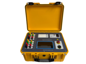
Click the image to know more about Transformer 50A DC Resistance Tester.
What Causes Transformer Winding Resistance?
Transformer winding resistance is determined by four core factors: conductor material properties, total wire length, cross-sectional area of the winding wire, and real-time operating temperature. Longer or narrower winding wires will elevate resistance values, while temperature fluctuations have a pronounced effect: for copper windings, resistance rises by roughly 0.4% with every 1°C increase in temperature. Additionally, subpar electrical connections or manufacturing defects can lead to abnormally high resistance readings, serving as early warning signs of underlying equipment issues.
|
Influencing Factor
|
Impact on Winding Resistance
|
Mitigation Approach
|
|---|---|---|
|
Conductor Material (Copper vs. Aluminum)
|
Copper: Lower resistance; Aluminum: Higher resistance
|
Opt for copper conductors in high-efficiency critical applications
|
|
Temperature Elevation
|
Approx. 0.4% increase per 1°C temperature rise
|
Deploy dedicated cooling systems to regulate operating temperature
|
|
Winding Wire Length
|
Longer windings correlate with higher resistance
|
Optimize winding geometry and design to reduce excess length
|
|
Wire Cross-Sectional Area
|
Smaller wire gauge leads to increased resistance
|
Select conductors with larger cross-sectional dimensions
|
How to Measure Transformer Winding Resistance Accurately?
Winding resistance testing is performed using a DC bridge or automated winding resistance tester, operating with low voltage and a stable direct current ranging from 1–10 amperes. Technicians must connect four-wire Kelvin probes to the transformer’s bushings, confirm the unit is fully de-energized, and compare measured readings to nameplate specifications standardized at 75°C. Each phase test generally takes 30 to 60 seconds to complete.
Temperature correction is mandatory for valid results, using the formula: $$R_t = R_m \times [1 + \alpha(T_t – T_m)]$$, where $$\alpha$$ denotes the temperature coefficient of the conductor material. For delta or wye-connected transformers, simultaneous multi-channel testing boosts operational efficiency. Any deviation from factory baseline data exceeding 2% is indicative of potential internal faults.
Why Is Winding Resistance Testing Indispensable for Transformers?
Routine winding resistance testing validates the structural integrity of transformer conductors, quantifies load-related energy losses, and identifies hidden defects such as inter-turn short circuits and loose terminal connections. Elevated resistance readings often signal equipment degradation caused by aging, excessive overloading, or initial manufacturing flaws. These tests are mandatory during transformer commissioning, scheduled maintenance, and post-repair inspections to guarantee safe and stable grid operation.
Notably, I²R copper losses can account for 20–30% of no-load losses in distribution transformers. Establishing baseline resistance data supports predictive maintenance protocols and correlates with thermal imaging results, allowing engineers to locate hotspots and mitigate failures before they escalate. Wrindu stresses the importance of high-precision testing to enhance global transformer reliability.
Common Issues Linked to Abnormal Transformer Winding Resistance
Typical abnormalities associated with faulty winding resistance include inter-turn short circuits, loose electrical connections, tap changer malfunctions, and chronic overheating. In delta-connected transformers, winding degradation in a single phase often triggers noticeable phase-to-phase resistance imbalances. Environmental stressors such as high humidity and metal oxidation also gradually increase resistance values over the transformer’s service life.
Tracking historical resistance trends is key to anomaly detection: a 1–2% incremental increase points to connection-related issues, while a rise exceeding 5% suggests potential short circuit risks. Wrindu recommends proactive preventive maintenance to resolve these problems and prolong transformer service life.
How Does Temperature Impact Winding Resistance?
Temperature exerts a direct influence on winding resistance due to thermal expansion and inherent material electrical properties. Standardizing all measurements to a reference temperature of 75°C ensures consistent, comparable results across tests. For copper windings, the refined temperature correction formula is:R2 = R1 * [234.5 + (T2 – 20)] / [234.5 + (T1 – 20)]. Correcting readings for temperature variations prevents misdiagnosis in high-temperature operating environments, protecting overall transformer operational safety.
Selecting the Optimal Test Current for Accurate Measurements
To avoid inductive measurement errors, the test DC current must be set below the transformer core saturation threshold—typically 5–20A for medium and large power transformers. Modern automated testers achieve current stability within one minute; higher test currents improve measurement precision, but must stay within manufacturer-defined safety limits. For large-scale transformer units, low-current DC bridge methods deliver sufficient accuracy. Technicians should continuously monitor voltage drops during testing to eliminate thermal interference and ensure data reliability.
Wrindu Expert Insights
“Transformer winding resistance testing is a cornerstone of operational safety and energy efficiency in power systems. Even minor fluctuations in resistance values can signal incipient faults or overheating in high-voltage infrastructure. At Wrindu, we engineer precision testing instruments that deliver consistent, repeatable measurements, empowering engineers to implement predictive maintenance and minimize unplanned downtime. Reliable resistance testing equips energy industry professionals and industrial operators alike to achieve unparalleled system performance and resilience.”— Wrindu Technical Consultant
Top Tools for Transformer Winding Resistance Testing
Industry-leading testing equipment includes automated and portable solutions tailored to diverse application scenarios: the Megger MWA300/330A for three-phase automated testing, the Vanguard TRM-403 for field portability, and the Raytech WR50 for dual-channel high-efficiency measurements. Ideal testing instruments should integrate built-in temperature correction and historical data trending functionalities.
Wrindu advises selecting testing equipment that aligns with the transformer’s kVA rating and winding configuration to maximize measurement accuracy.
Troubleshooting High Transformer Winding Resistance
To resolve elevated winding resistance readings, start by inspecting all terminal connections and retorquing fastening bolts, then retest individual phases independently. For three-phase transformers, compare phase-to-phase loop resistance values to isolate irregularities. Persistently high resistance after initial checks may require winding disassembly to detect short circuits or incorrect turn counts. Leveraging historical data trending and software-based monitoring enables targeted investigation of deviations exceeding 3% from baseline values.
Key Takeaways
A thorough understanding of transformer winding resistance is essential for cutting energy losses, boosting operational efficiency, and maintaining safe power system performance. Core best practices include conducting routine resistance tests, applying standardized temperature corrections, utilizing automated precision testers, and tracking long-term measurement trends. Wrindu’s expertise in high-precision electrical measurement equips engineers worldwide to build and maintain reliable, energy-efficient power systems.
Frequently Asked Questions (FAQs)
What Is Transformer Winding Resistance?
Transformer winding resistance is the DC-based opposition to current flow within the copper or aluminum coils of a transformer, driven by conductor material properties and wire length. Measured via low-voltage DC testing, it reveals connection integrity, winding turn accuracy, and internal faults like short circuits. This parameter is critical for calculating energy efficiency and heat loss in power systems.
How Is Transformer Winding Resistance Defined?
It is defined as the pure ohmic resistance (calculated via $$R = V/I$$) of transformer windings, excluding inductive reactance effects. DC testing produces micro-ohm level readings, with lower values indicating reduced copper losses. It is widely used to verify manufacturing quality, tap changer performance, and phase balance during equipment commissioning.
A Simple Explanation of Transformer Coil Resistance
Coil resistance stems from conductor resistivity, total number of winding turns, and wire cross-section—following the fundamental principles of Ohm’s Law. Elevated resistance translates to increased I²R heat generation and reduced energy efficiency. A basic DC resistance test compares phase-to-phase values, with imbalances signaling potential equipment defects.
Winding Resistance in Power Transformers
For high-capacity power transformers, winding resistance measurements assess the integrity of primary and secondary coils in grid-scale equipment. Testing across all tap positions ensures uniform resistance distribution, while abnormal deviations point to loose joints or internal short circuits. This parameter is vital for evaluating load losses and temperature rise characteristics.
Basic Principles of Transformer Resistance Testing
The core principle relies on Ohm’s Law: a stable DC current passed through windings generates a measurable voltage drop, once inductive transient effects dissipate. The four-wire Kelvin method eliminates lead resistance errors for precise readings. Temperature-corrected baseline values serve as a reference for tracking long-term equipment degradation.
A Guide to Transformer Winding Ohmic Resistance
Ohmic resistance refers to the steady-state DC resistance value recorded after transient L/R time constant effects subside. Technicians apply a stable DC current, wait for signal stabilization (ranging from seconds to minutes), and compute resistance via voltage-current ratio. This guides fault diagnosis for utility providers and original equipment manufacturers, often using Wrindu precision testing tools.
Entry-Level Knowledge of Transformer Resistance Testing
Beginners should master these fundamentals: winding resistance reflects conductive material properties; tests require a fully de-energized transformer and micro-ohmmeter; phase-to-phase comparison identifies irregularities; and all readings must be corrected to the 75°C reference temperature. This foundational testing prevents unplanned outages by detecting defects early for substation technicians.
Why Measure Transformer Winding Resistance?
Winding resistance testing detects poor connections, shorted turns, tap changer faults, and phase imbalances before catastrophic failures occur. It enables accurate copper loss calculations, validates winding turn ratios, and assesses post-repair equipment health. This testing is vital for reliability in power grids, renewable energy systems, and industrial setups, delivering cost savings with Wrindu precision instrumentation.
