What Is a CT Magnetization Curve Test and How Is It Performed?
Learn how a CT magnetization curve test works, how to find knee-point voltage, and how IEC 61869 ensures accurate current transformer protection and metering.

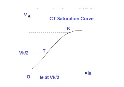
A CT magnetization curve test evaluates the magnetic performance of a current transformer (CT) core by applying a gradually increasing AC voltage to the secondary winding while keeping the primary circuit open.
As the voltage rises, the excitation (magnetizing) current is recorded and plotted against the applied voltage. The resulting curve identifies the knee point voltage, where a small increase in voltage causes a sharp rise in excitation current.
This curve reveals the CT’s core saturation characteristics and confirms whether the transformer can operate accurately within its specified range for metering or protection applications.
Click the picture to know more about Wrindu CT and PT Analyzer.
How Is a CT Magnetization Curve Test Performed?
The test procedure is straightforward but requires precision:
-
Connect the test set to the CT secondary terminals.
-
Keep the primary winding open (no primary current).
-
Gradually increase the AC voltage from zero.
-
Measure and record excitation current at each voltage step.
-
Identify the knee point, typically defined (per standards) as the voltage where a 10% rise in voltage produces approximately a 50% increase in excitation current.
-
Record readings above and below the knee point for curve accuracy.
-
Reduce voltage back to zero to demagnetize the core and remove residual flux.
Modern CT and PT analyzers automate this entire sequence, ensuring stable voltage control, automatic knee-point detection, and digital curve plotting.
What Does the Knee Point Indicate?
The knee point marks the beginning of core saturation. Below this point, the CT operates in a linear region where measurement and protection accuracy are maintained.
Beyond the knee point, excitation current rises steeply, and the CT can no longer reproduce primary current accurately.
For protection CTs, an appropriate knee-point voltage is critical. If the CT saturates too early during a fault, protection relays may misoperate or fail to trip.
Relevant Standards for CT Magnetization Testing
Two key international standards govern CT testing:
-
IEC 61869 – Defines performance, knee-point voltage, and accuracy classes for instrument transformers.
-
IEEE C57.13 – Specifies performance requirements for CTs in North America.
These standards outline acceptable saturation limits, excitation characteristics, and accuracy classes for both metering and protection CTs.
Who Uses CT Magnetization Curve Testing?
CT magnetization testing is widely used by:
-
Power utilities
-
Substation commissioning teams
-
Transformer and switchgear manufacturers
-
Independent testing laboratories
-
Protection relay engineers
It is essential during:
-
Factory acceptance testing (FAT)
-
Commissioning of substations
-
Routine maintenance
-
Post-repair verification
-
Aging asset diagnostics
Why OEM Customization Matters in CT Test Equipment
For large utilities and OEM factories, standardized equipment may not meet all operational needs. Custom-built analyzers can offer:
-
Extended voltage output ranges
-
Advanced software reporting
-
Integration with asset management systems
-
Custom test templates
-
Multiple communication interfaces (USB, RS232, LAN)
OEM flexibility improves workflow efficiency and ensures compliance with local grid codes and reporting standards.
When Should CT Magnetization Curve Tests Be Conducted?
CT magnetization curve tests should be performed:
-
During manufacturing and final inspection
-
Before commissioning in substations
-
After transport or mechanical impact
-
After repair or rewinding
-
Periodically as part of preventive maintenance
Regular testing helps detect:
-
Core degradation
-
Insulation deterioration
-
Winding deformation
-
Contamination or moisture issues
Early detection reduces unexpected failures and relay maloperation.
How to Interpret a CT Magnetization Curve
A typical magnetization curve contains three regions:
-
Linear Region – Low excitation current, stable magnetic behavior.
-
Knee Point Region – Transition area where saturation begins.
-
Saturation Region – Rapid current increase, loss of accuracy.
Warning signs include:
-
Lower-than-expected knee-point voltage
-
Excessive magnetizing current
-
Irregular curve shape
These deviations may indicate core damage or insulation defects.
Digital Advancements in CT Magnetization Testing
Modern CT analyzers now include:
-
Touchscreen interfaces
-
Automatic knee-point calculation
-
Real-time waveform analysis
-
PC-based data management
-
USB and cloud data export
-
Automated demagnetization cycles
Advanced systems can complete a full magnetization curve test in under one minute while maintaining high accuracy.
Applications in Power Systems
CT magnetization curve testing supports:
-
Relay protection system validation
-
Transformer differential protection
-
Overcurrent protection verification
-
Grid fault analysis
-
Asset lifecycle management
It is especially important in high-fault-current networks where CT saturation can compromise system stability.
