Step-by-Step Guide to Use 4-Wire Kelvin Method
Step-by-Step 4-Wire Kelvin Method for high-precision low-resistance measurement. Check best tools for 4-wire Kelvin measurement, standard wiring norms & professional Kelvin test lead setup.
The 4-wire Kelvin method (also called four-terminal sensing) is a gold-standard technique for high-precision low-resistance measurements, widely used in electronics testing, battery maintenance, industrial electrical inspection and component calibration. Unlike the 2-wire method, it eliminates errors caused by test lead resistance and contact resistance, delivering reliable readings even for milliohm and microohm-level resistances. Below is a complete, practical step-by-step guide covering tool preparation, standardized wiring and operational procedures, with targeted tips to ensure measurement accuracy.
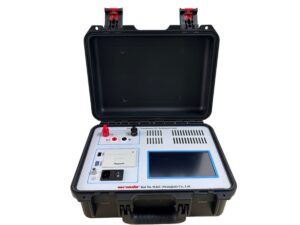
Click the image to know more about Wrindu DC Resistance Tester.
Essential Tool Preparation for 4-Wire Kelvin Measurement
Before starting the measurement, prepare qualified tools to avoid inaccurate data or equipment damage. Prioritize professional, matching kits—refer to best tools for 4-wire Kelvin measurement for top-rated, cost-effective options tailored to different testing scenarios.
-
4-Wire Compatible Measuring Instrument: A dedicated Kelvin resistance tester, precision multimeter with 4-wire resistance mode, or milliohm meter is required. Standard multimeters without 4-wire function cannot realize true Kelvin measurement; verify the device has separate current-source and voltage-sense terminals.
-
Specialized Kelvin Test Leads & Clips: Use 4-wire Kelvin test leads (color-coded for easy identification, typically red/black for current, white/blue for voltage) and insulated Kelvin clips. These clips isolate current and voltage paths, avoiding cross-interference—follow Kelvin test lead setup best practices to optimize wiring efficiency and stability.
-
Auxiliary Tools: Clean cloth, alcohol swabs (for removing oxidation/oil on contact points), anti-static wristband (for precision electronic component testing), and fixed brackets (to secure the device under test, DUT) to prevent loose connections during testing.
Core Wiring Norms for 4-Wire Kelvin Setup
Wiring non-compliance is the top cause of Kelvin measurement failure. Strictly follow the “separate current and voltage paths” principle, with voltage-sense leads connectedinside current leads to exclude lead resistance from the reading.
Basic Wiring Rules
-
Current Leads (Force Leads): Connect the positive current lead to one end of the DUT, and the negative current lead to the opposite end. These leads carry the test current, so use thick, low-resistance wires to reduce voltage drop.
-
Voltage-Sense Leads (Sense Leads): Connect the positive sense lead adjacent to the positive current lead on the DUT, and the negative sense lead adjacent to the negative current lead. Ensure sense leads make direct, tight contact with the DUT, with no gap between current and sense contacts.
-
Anti-Interference Norms: Keep test leads short and tidy; avoid overlapping current and sense leads, and keep them away from high-power equipment to reduce electromagnetic interference (EMI). Do not touch leads during measurement to avoid signal fluctuation.
Standard Color-Coded Wiring Reference
|
Lead Color
|
Function
|
Wiring Position
|
|---|---|---|
|
Red
|
Positive Current (I+)
|
One end of the DUT (outer terminal)
|
|
Black
|
Negative Current (I-)
|
Opposite end of the DUT (outer terminal)
|
|
White
|
Positive Voltage (V+)
|
Inner side of red current lead (DUT contact point)
|
|
Blue
|
Negative Voltage (V-)
|
Inner side of black current lead (DUT contact point)
|
Step-by-Step Operational Process
Step 1: Pre-Test Preparation & DUT Handling
First, power off the DUT and discharge capacitive components to prevent electric shock or equipment burnout. Clean the DUT contact points with an alcohol swab to remove oxidation, dust or oil stains—poor contact will introduce extra resistance and skew results. Wear an anti-static wristband if testing sensitive electronic components, and fix the DUT with a bracket to avoid movement during wiring and testing.
Step 2: Complete Kelvin Test Lead Setup
Follow the wiring norms above to connect the Kelvin test leads to the measuring instrument and DUT: plug the current leads into the instrument’s current-source terminals, and the sense leads into the voltage-sense terminals. Double-check all connections are tight and correct, with no reversed polarity or crossed leads. Confirm the clips firmly clamp the DUT, ensuring full electrical contact without gaps.
Step 3: Instrument Parameter Configuration
Turn on the measuring instrument and switch it to 4-Wire Kelvin Resistance Mode (avoid 2-wire mode). Select the appropriate resistance range based on the DUT’s estimated resistance (start with a higher range to prevent over-range damage, then fine-tune). Set a suitable test current: lower current for small, heat-sensitive components, higher current for low-resistance samples to improve signal-to-noise ratio. Calibrate the instrument if it hasn’t been used recently, following the manufacturer’s instructions.
Step 4: Perform the Measurement
Keep the test environment stable (avoid vibration, temperature extremes and EMI), and do not touch the leads or DUT. Activate the measurement function, wait 3-5 seconds for the reading to stabilize, then record the displayed resistance value. Take 2-3 repeated measurements and calculate the average to reduce random errors; discard obvious abnormal readings.
Step 5: Post-Measurement Handling
After completing the measurement, turn off the instrument first, then disconnect the test leads from the DUT (reverse the wiring order). Organize the test leads and clips, clean the DUT and workbench, and store the instrument in a dry, dust-free environment. Record the measurement data, test conditions (temperature, humidity) and DUT information for future traceability.
Key Tips for Accurate 4-Wire Kelvin Measurement
-
Always use dedicated Kelvin leads and clips; ordinary test leads cannot eliminate lead resistance errors, even with a 4-wire instrument.
-
Minimize the distance between current and sense contacts on the DUT—wider spacing will include excess DUT resistance in the reading.
-
Avoid long test leads; longer leads increase resistance and EMI interference, compromising measurement precision.
-
Calibrate the measuring instrument regularly (every 6-12 months) to maintain long-term accuracy, especially for high-precision testing scenarios.
-
For ultra-low resistance measurements (below 1mΩ), use a constant-temperature environment to offset the impact of thermal resistance on results.
The 4-wire Kelvin method is ideal for measuring low resistances such as battery internal resistance, shunt resistors, cable resistance and welding joint resistance. By following this guide, strictly adhering to wiring norms and using qualified tools, you can achieve stable, high-precision measurement results efficiently.
