

How to Perform Ground Resistance Testing for Electrical Safety and Reliable Grounding Systems?
Learn how to perform ground resistance testing step by step. Discover testing methods, equipment requirements, electrode placement, and tips for accurate grounding measurements.
Why Is Proper Ground Resistance Testing Important?
A grounding system is one of the most important safety components in electrical installations.
It provides a safe path for fault current to flow into the earth and helps reduce risks caused by:
- Electrical faults
- Lightning surges
- Equipment insulation failure
- Leakage current
However, a grounding system cannot be considered reliable only because it has been installed correctly.
Regular ground resistance testing is required to verify whether the grounding system still performs effectively during operation.
A professional ground resistance test helps engineers identify hidden problems before they cause equipment damage or safety hazards.
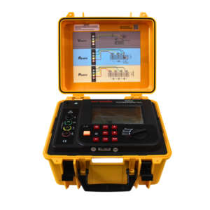
Click the picture to know more about Wrindu Earth Resistance Tester.
What Equipment Is Needed for Ground Resistance Testing?
To perform accurate grounding measurements, engineers need suitable testing equipment and accessories.
The main instrument used is a ground resistance tester, also called an earth resistance tester.
A complete testing setup usually includes:
Ground Resistance Tester
The tester generates a controlled test current and measures the voltage response from the grounding system.
Modern instruments may provide:
- Automatic resistance calculation
- Digital measurement display
- Noise interference rejection
- Data storage functions
Auxiliary Electrodes
Ground resistance testing normally requires additional electrodes placed in the soil.
They include:
- Current electrode
- Potential electrode
These electrodes create a temporary measurement circuit with the grounding system.
Test Cables
High-quality cables ensure stable signal transmission and reduce measurement errors during field testing.
How Do You Prepare Before Performing a Ground Resistance Test?
Proper preparation improves measurement accuracy and prevents incorrect results.
Inspect the Grounding System
Before testing, engineers should check:
- Ground conductor condition
- Connection points
- Electrode corrosion
- Visible damage
Damaged grounding components may affect test results.
Select a Suitable Testing Location
The testing area should avoid strong electrical interference sources such as:
- Power transformers
- High-voltage cables
- Large motors
A clean testing environment helps improve measurement stability.
Check Weather and Soil Conditions
Soil conditions influence grounding measurements.
Engineers should record:
- Soil moisture
- Temperature
- Recent weather conditions
This information helps compare future test results.
How Is the Ground Resistance Test Performed Step by Step?
Step 1: Disconnect the Grounding System if Required
Some grounding systems need to be isolated from parallel paths before measurement.
This ensures that the tester evaluates the actual grounding electrode resistance.
Step 2: Install Auxiliary Electrodes
The current electrode and potential electrode are installed at suitable distances from the grounding electrode.
Correct spacing helps avoid overlapping resistance areas.
Step 3: Connect the Testing Equipment
The tester is connected between:
- Ground electrode under test
- Current electrode
- Potential electrode
Step 4: Start the Measurement
The instrument injects a test current into the earth.
The voltage response is measured automatically.
Step 5: Analyze the Result
The final resistance value is displayed on the tester.
Engineers compare the result with:
- Design requirements
- Industry standards
- Previous measurement records
What Factors Can Cause Incorrect Ground Resistance Test Results?
Accurate testing requires careful control of testing conditions.
Incorrect Electrode Distance
If auxiliary electrodes are placed too close, measurement zones may overlap.
This can create inaccurate readings.
Poor Ground Contact
Loose or improperly installed electrodes may increase contact resistance.
Underground Metal Structures
Nearby pipelines or buried cables may affect current distribution in the soil.
Electrical Noise
High-voltage equipment can introduce interference during measurement.
Advanced ground resistance testers with noise filtering can reduce these effects.
How Can Engineers Improve Ground Resistance Testing Accuracy?
Reliable measurement requires:
- Correct testing method selection
- Proper electrode placement
- Stable test connections
- Multiple measurement verification
For critical electrical systems, engineers often perform repeated tests by changing electrode positions to confirm result consistency.
FAQs About Ground Resistance Testing Procedure
How do you perform a ground resistance test?
A ground resistance test is performed by connecting a ground resistance tester to the grounding electrode and auxiliary electrodes, applying test current, and calculating resistance from measured voltage and current.
What equipment is used for earth resistance testing?
An earth resistance tester, test cables, and auxiliary ground electrodes are commonly required.
Why does electrode spacing affect ground resistance testing?
Electrode spacing determines the accuracy of the measured earth resistance by controlling current distribution in the soil.
Can ground resistance testing be performed without disconnecting the grounding system?
Yes. Clamp-on ground resistance testers can measure grounding resistance without disconnecting certain grounding systems.
How can I improve ground resistance measurement accuracy?
Using correct electrode distances, avoiding interference sources, and selecting professional testing equipment can improve accuracy.
