

Complete Guide to Transformer Winding Resistance Testing: Standards and Best Practices
Learn how to perform a transformer winding resistance test, including testing methods, IEEE and IEC standards, data analysis, temperature correction, and fault diagnosis.
Power grids rely on transformers to keep electricity flowing smoothly. To make sure these massive machines stay healthy, engineers use a critical diagnostic tool: the winding resistance test. This guide breaks down what this test is, why it matters, and how to perform it accurately according to global standards.
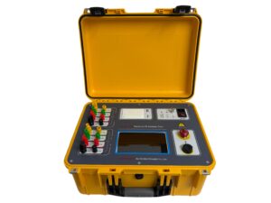
Click the image to know more about Transformer DC Resistance Tester.
What is a Transformer Winding Resistance Test?
A winding resistance test calculates the DC resistance of a transformer’s internal coils. Technicians inject a low DC voltage combined with a high current through the windings. By measuring the voltage drop, they can calculate the resistance using Ohm’s Law.
This test checks the physical integrity of internal connections. It is highly effective at spotting loose joints, broken strands, internal short circuits, and faults within tap changers. International engineering guidelines like IEEE C57.12.90 and IEC 60076-1 govern how these tests are conducted to ensure safety and precision.
Why do Engineers Measure Winding Resistance?
Regular testing prevents sudden equipment failure and catastrophic power outages. Over time, factors like heat, vibration, and age can degrade electrical joints. Measuring winding resistance helps maintenance teams:
-
Catch internal damage early: Identify high-resistance corrosion or low-resistance short circuits before they cause a breakdown.
-
Evaluate tap changers: Verify that On-Load Tap Changers (OLTC) transition smoothly and maintain good contact across all positions.
-
Calculate power efficiency: Provide the exact resistance numbers needed to determine $I^2R$ conductor losses.
-
Establish a baseline: Create a data history to track the transformer’s wear and tear over its lifespan.
How do you Perform the Test Correctly?
Getting highly accurate data requires proper prep work and the right execution steps:
-
Isolate and Cooldown: Disconnect the transformer from the grid entirely. Let it sit for 3 to 4 hours so the internal oil temperature stabilizes evenly.
-
Hook up the Leads: Connect the test equipment using a Kelvin connection (four-wire setup) to eliminate lead resistance errors.
-
For Star (Y) windings, measure from the neutral terminal to each phase line.
-
For Delta windings, measure line-to-line. Because delta phases are interconnected, multiply the line-to-line reading by 1.5 to find the per-phase resistance.
-
-
Inject the DC Current: Apply a test current that does not exceed 15% of the winding’s rated current. This cap prevents the test current from heating up the wires and skewing the data.
-
Wait for Saturation: Large transformers take time to stabilize magnetically. Advanced testing units use dual-injection methods to saturate the core up to 50% faster.
-
Demagnetize: Always run a demagnetization routine after testing to clear out residual magnetism, which could otherwise cause massive inrush currents when restarting the transformer.
How do you Analyze Winding Resistance Data?
Raw measurements cannot be compared directly if they were taken at different temperatures. Resistance changes as the transformer warms up or cools down.
To compare new results with factory baselines, you must mathematically correct the data to a standard reference temperature of 75°C using the average oil temperature.
-
Normal condition: If the temperature-corrected values are within 1% to 2% of the original factory data, the winding is in good shape.
-
Abnormal condition: A difference higher than 2% indicates a serious anomaly, such as a failing connection or an uneven phase, requiring immediate investigation.
Frequently Asked Questions
How often should power plants test transformer windings?
For critical infrastructure, test the windings annually during routine maintenance. You should also run this test immediately after initial installation or right after an electrical fault occurs to check for hidden damage.
Can this test diagnose on-load tap changer (OLTC) issues?
Yes. By measuring the resistance across every single tap position, you can verify if the contacts are eroding or if the tap changer mechanism is failing to seat properly.
What causes a high resistance reading in a transformer?
High resistance usually points to loose internal connection straps, oxidized joints, corroded terminals, or broken copper strands inside the winding coils.
Why is temperature correction to 75°C necessary?
Copper and aluminum conductors increase in resistance as temperature rises. Correcting all field readings to a standard 75°C ensures that you are comparing data under identical thermal conditions, eliminating weather and operating variables.
