

What Are the Different Ground Resistance Testing Methods and When Should They Be Used?
Learn different ground resistance testing methods, including 3-point fall-of-potential, 4-point soil resistivity, clamp-on, and selective testing. Discover how to choose the right method for substations, transformers, and electrical systems.
- BYwrindu
- On
- InTechnical FAQs
Ground resistance testing is an essential process for checking the performance and safety of electrical grounding systems.
A grounding system must provide a reliable path for fault current, lightning current, and leakage current to flow safely into the earth.
However, different grounding applications require different testing methods.
A small grounding rod, a transformer grounding system, and a large substation earth grid cannot always be evaluated using the same approach.
Selecting the correct ground resistance testing method helps engineers obtain accurate results and maintain electrical safety.
The most common ground resistance testing methods include:
- 3-point fall-of-potential testing
- 4-point soil resistivity testing
- Clamp-on ground resistance testing
- Selective ground resistance testing
These methods are widely used in:
- Power substations
- Transformer grounding systems
- Industrial facilities
- Renewable energy plants
- Communication towers
- Electrical installations
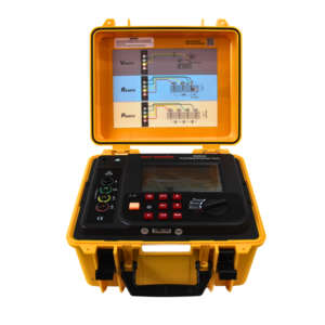
Click the picture to know more about Wrindu Earth Resistance Tester.
Why Are Different Ground Resistance Testing Methods Required?
Different grounding systems have different structures, sizes, and operating environments.
For example:
A single grounding rod requires a different measurement approach compared with a large substation grounding grid.
The choice of testing method depends on:
- Grounding system design
- Testing purpose
- Required accuracy
- Available testing space
- Site conditions
Using the correct method helps engineers:
- Obtain reliable measurements
- Reduce testing errors
- Identify grounding problems
- Improve electrical safety
What Is the 3-Point Fall-of-Potential Ground Resistance Test Method?
The 3-point fall-of-potential method is one of the most commonly used methods for measuring grounding resistance.
It evaluates the resistance between a grounding electrode and the surrounding earth.
This method uses three connection points:
- Test electrode (E)
- Potential electrode (P)
- Current electrode (C)
The ground resistance tester applies a controlled AC current through the earth and measures the voltage drop.
The resistance value is calculated using:
R = V / I
Where:
- R = Ground resistance
- V = Voltage drop
- I = Test current
How Does the 3-Point Method Measure Ground Resistance?
During the test:
- The tester sends current from the grounding electrode to the current electrode.
- The potential electrode measures voltage changes in the soil.
- The instrument calculates resistance automatically.
The result represents the actual resistance of the grounding system.
What Are the Advantages of the 3-Point Ground Resistance Test?
The main advantages include:
High Measurement Accuracy
The method directly evaluates the relationship between current flow and voltage drop.
Suitable for Many Applications
It can be used for:
- Ground rods
- Transformer grounding
- Substation grounding grids
- Industrial grounding systems
Widely Accepted Method
The fall-of-potential method is recognized by many electrical engineers and utility companies.
What Are the Limitations of the 3-Point Method?
Although accurate, this method requires:
- Auxiliary electrodes
- Sufficient testing distance
- Proper electrode placement
It may be difficult to perform in areas with limited space.
What Is the 4-Point Soil Resistivity Testing Method?
The 4-point method is mainly used to measure soil resistivity.
Unlike the 3-point method, it does not directly measure the resistance of an existing grounding electrode.
Instead, it evaluates how easily electrical current can flow through the soil.
Soil resistivity testing is especially important before designing new grounding systems.
How Does the 4-Point Soil Resistivity Test Work?
The 4-point method uses four electrodes placed in a straight line:
- Two current electrodes
- Two potential electrodes
During measurement:
- Current is injected into the soil through the outer electrodes.
- Voltage is measured through the inner electrodes.
- The tester calculates soil resistivity.
Why Is Soil Resistivity Important for Grounding System Design?
Soil resistivity directly affects grounding performance.
High soil resistivity may result in:
- Higher grounding resistance
- Poor fault current discharge
- Increased grounding design difficulty
Engineers use soil resistivity data to determine:
- Ground electrode depth
- Ground grid size
- Number of grounding conductors
Where Is the 4-Point Method Commonly Used?
The 4-point method is often used for:
- New substation construction
- Solar power projects
- Wind energy systems
- Large industrial facilities
- Power plant grounding design
What Is the Clamp-On Ground Resistance Testing Method?
Clamp-on ground resistance testing is a convenient method that allows engineers to measure grounding resistance without disconnecting grounding conductors.
A clamp ground resistance tester uses an induction clamp around the grounding conductor.
This method is commonly used for maintenance testing.
How Does Clamp-On Ground Resistance Testing Work?
During testing:
- The clamp generates a test signal.
- The signal passes through the grounding loop.
- The tester measures the resistance value.
Unlike traditional methods, auxiliary electrodes are not required.
What Are the Benefits of Clamp Ground Resistance Testing?
The main advantages include:
Fast Testing
Engineers can complete measurements quickly.
No Need to Disconnect Grounding Connections
This reduces system downtime.
Suitable for Maintenance Work
It is useful for:
- Building grounding systems
- Distribution networks
- Multiple grounding points
What Are the Limitations of Clamp-On Testing?
Clamp testing requires:
- A closed grounding loop
- Multiple grounding paths
It is not suitable for:
- Single isolated grounding rods
- New grounding system design
- Soil resistivity measurement
What Is Selective Ground Resistance Testing?
Selective ground resistance testing is designed for complex grounding systems with multiple grounding paths.
It combines traditional testing principles with clamp measurement technology.
This method allows engineers to measure individual grounding electrodes without completely disconnecting the grounding system.
How Does Selective Ground Testing Work?
Selective testing usually requires:
- Ground resistance tester
- Current clamp
- Test cables
- Auxiliary electrodes
The tester separates the current contribution of each grounding path.
This provides more detailed information about individual grounding components.
Where Is Selective Ground Resistance Testing Used?
Selective testing is commonly used in:
- Large substations
- Communication towers
- Industrial power systems
- Complex grounding networks
How Do Different Ground Resistance Testing Methods Compare?
| Testing Method | Main Purpose | Best Application |
|---|---|---|
| 3-Point Method | Measure grounding resistance | Ground rods, transformers, substations |
| 4-Point Method | Measure soil resistivity | Grounding system design |
| Clamp Method | Fast resistance measurement | Maintenance testing |
| Selective Method | Individual electrode measurement | Large grounding networks |
How Should Engineers Choose the Right Ground Resistance Testing Method?
Choosing the correct testing method depends on the actual application.
Which Testing Method Is Best for Grounding Rods?
For individual grounding rods, the 3-point fall-of-potential method is usually the preferred option.
It provides direct measurement of the electrode-to-earth resistance.
Which Testing Method Is Best for Substations?
Substations often require:
- 3-point testing
- Selective testing
- Soil resistivity testing
The selected method depends on grounding system size and maintenance requirements.
Which Testing Method Is Best for Maintenance Inspection?
For quick inspection of existing grounding systems:
- Clamp testing
- Selective testing
can improve efficiency because they reduce the need for system disconnection.
How Can Wrindu Ground Resistance Testers Support Different Testing Applications?
Wrindu provides professional electrical testing solutions for grounding system inspection and maintenance.
Wrindu earth resistance testers are designed for:
- Ground resistance measurement
- Soil resistivity testing
- Field grounding inspection
- Electrical safety evaluation
Key advantages include:
- Accurate measurement
- Stable performance
- Portable design
- Easy operation
Wrindu testing equipment helps engineers improve grounding reliability in:
- Power utilities
- Industrial facilities
- Renewable energy projects
FAQs
What is the most accurate ground resistance testing method?
The 3-point fall-of-potential method is widely considered one of the most accurate methods for measuring grounding resistance.
What is the difference between 3-point and 4-point ground resistance testing?
The 3-point method measures grounding electrode resistance, while the 4-point method measures soil resistivity for grounding system design.
Can a clamp ground resistance tester replace the fall-of-potential method?
No. Clamp testing is convenient for maintenance but is not suitable for all grounding systems.
Which method is used to test transformer grounding resistance?
Transformer grounding systems are commonly tested using the 3-point method or selective ground resistance testing.
Why is soil resistivity testing needed before grounding installation?
Soil resistivity testing helps engineers design effective grounding systems by understanding underground electrical conditions.
Can ground resistance testing be performed without disconnecting the ground wire?
Yes. Clamp and selective testing methods allow measurement without complete disconnection.
What factors affect ground resistance test results?
Common factors include:
- Soil moisture
- Soil composition
- Electrode spacing
- Electrical interference
- Grounding system condition
Conclusion
Different ground resistance testing methods provide solutions for different electrical grounding applications.
The 3-point fall-of-potential method remains one of the most reliable methods for measuring grounding resistance.
The 4-point method helps engineers understand soil conditions before designing grounding systems, while clamp and selective methods improve testing efficiency for existing electrical networks.
By selecting the correct testing method and using professional equipment such as Wrindu ground resistance testers, engineers can improve grounding safety, reduce electrical risks, and maintain reliable power system operation.
