

3-Point Fall-of-Potential Method Explained: How to Measure Ground Resistance Accurately
Learn how the 3-point fall-of-potential method works, how to perform a ground resistance test, electrode placement rules, measurement principles, and common testing mistakes.
What Is the 3-Point Ground Resistance Test Method?
The 3-point ground resistance test is a widely used method for measuring the resistance of an electrical grounding system.
Also called the fall-of-potential method, this testing method evaluates how effectively a grounding electrode transfers fault current into the earth.
A grounding system must provide a low-resistance path for unwanted electrical currents, including:
- Fault current
- Lightning current
- Leakage current
If the grounding resistance is too high, electrical protection systems may not operate correctly, increasing risks to equipment and personnel.
The 3-point method helps engineers verify whether grounding systems meet safety requirements and maintain reliable performance.
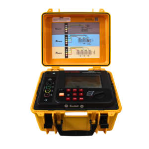
Click the picture to know more about Wrindu Earth Resistance Tester.
Why Is the Fall-of-Potential Method Used for Ground Resistance Testing?
The fall-of-potential method is one of the most trusted techniques because it directly measures the relationship between current flow and voltage drop in the soil.
Unlike simple continuity testing, it evaluates the actual resistance between the grounding system and the earth.
What Are the Main Advantages of the 3-Point Method?
The main benefits include:
Accurate Ground Resistance Measurement
The method measures the voltage generated by a known test current flowing through the earth.
This allows the tester to calculate the actual grounding resistance value.
Suitable for Different Grounding Systems
The 3-point method can be used for:
- Single grounding rods
- Multiple grounding electrodes
- Transformer grounding systems
- Substation grounding grids
- Industrial grounding networks
Widely Accepted for Electrical Testing
The fall-of-potential method is commonly used by electrical engineers, utilities, and maintenance teams because of its reliable measurement principle.
How Does the 3-Point Fall-of-Potential Method Work?
The working principle of the 3-point ground resistance test is based on Ohm’s Law:
R = V / I
Where:
- R = Ground resistance
- V = Voltage measured between electrodes
- I = Test current flowing through the soil
During the test, the ground resistance tester creates a temporary electrical circuit through the earth.
How Does the Tester Measure Ground Resistance?
The testing process includes three main actions:
- The instrument sends a controlled current between the test electrode and current electrode.
- The tester measures the voltage difference between the test electrode and potential electrode.
- The instrument calculates the resistance value automatically.
The final result represents the resistance of the grounding system under actual site conditions.
What Are the Three Electrodes Used in a 3-Point Ground Resistance Test?
The accuracy of the test depends on the correct arrangement of three electrodes.
What Is the Test Electrode (X)?
The test electrode is the grounding system being evaluated.
Examples include:
- Transformer grounding point
- Substation grounding grid
- Equipment grounding conductor
The resistance between this electrode and the earth is the value that needs to be measured.
What Is the Current Electrode (C)?
The current electrode creates the path for the test current.
During measurement:
- Current flows from the test electrode to the current electrode through the soil.
- The tester uses this current path to evaluate grounding resistance.
The current electrode must be placed far enough away to avoid overlapping resistance areas.
What Is the Potential Electrode (P)?
The potential electrode measures the voltage drop between the test electrode and the earth.
Its position directly affects measurement accuracy.
In many applications, the potential electrode is placed at approximately 62% of the distance between the test electrode and current electrode.
How Do You Perform a 3-Point Ground Resistance Test Step by Step?
Correct testing procedures are important for obtaining reliable results.
Step 1: Prepare the Grounding System
Before testing:
- Identify the grounding electrode
- Check test equipment condition
- Confirm connection points
For critical electrical systems, parallel grounding paths may need to be disconnected to avoid measurement errors.
Step 2: Install the Auxiliary Electrodes
Place the:
- Current electrode (C)
- Potential electrode (P)
into the soil according to recommended spacing requirements.
The electrodes should normally be placed in a straight line to improve measurement consistency.
Step 3: Connect the Ground Resistance Tester
Connect the test leads:
- X terminal → Grounding system under test
- P terminal → Potential electrode
- C terminal → Current electrode
Ensure all connections are tight and stable.
Step 4: Apply Test Current and Measure Voltage
The tester applies a controlled AC test current into the soil.
At the same time, it measures the voltage difference between the test electrode and potential electrode.
Step 5: Calculate and Verify the Result
The instrument calculates the grounding resistance automatically.
Engineers should verify:
- Stable readings
- Correct electrode placement
- Repeatable measurement results
Why Is Electrode Placement Important in Ground Resistance Testing?
Electrode positioning is one of the most important factors affecting measurement accuracy.
Every grounding electrode creates a resistance area around it in the soil.
If the electrodes are installed too close together:
- Resistance areas may overlap.
- The measured value may not represent the actual grounding resistance.
Proper spacing allows the tester to measure the true voltage drop caused by the grounding system.
What Is the 62% Rule in the Fall-of-Potential Method?
The 62% rule is a commonly used guideline for placing the potential electrode.
The potential electrode is positioned at approximately:
62% of the distance between the test electrode and current electrode
For example:
If the current electrode is installed 30 meters from the test electrode:
- Potential electrode position ≈ 18.6 meters from the test electrode
This location usually provides a stable measurement point where the influence of both electrodes is minimized.
What Factors Affect the Accuracy of a 3-Point Ground Resistance Test?
Several environmental and installation conditions can influence measurement results.
How Does Soil Resistivity Affect Ground Resistance Testing?
Soil characteristics directly affect how electrical current flows.
Important factors include:
- Soil moisture
- Soil composition
- Temperature
- Seasonal changes
For example:
- Wet soil usually has lower resistance.
- Dry soil usually has higher resistance.
How Does Electrode Condition Affect Measurement Results?
The condition of grounding electrodes can influence test accuracy.
Common issues include:
- Corrosion
- Loose connections
- Poor contact with soil
- Damaged grounding conductors
Regular inspection helps maintain reliable grounding performance.
How Does Electrical Interference Affect Testing?
Nearby electrical equipment may introduce unwanted signals.
Possible sources include:
- Power transformers
- Transmission lines
- Industrial machinery
Using a professional ground resistance tester with interference rejection capability can improve measurement reliability.
What Are Common Mistakes During a 3-Point Ground Resistance Test?
Incorrect Electrode Distance
Placing auxiliary electrodes too close to the test electrode may create inaccurate results.
Solution:
Follow recommended spacing guidelines and verify measurement stability.
Poor Connection Between Tester and Electrodes
Loose connections can cause unstable readings.
Solution:
Check all test cables and electrode connections before measurement.
Ignoring Environmental Conditions
Soil conditions can change measurement results.
Solution:
Record:
- Weather conditions
- Soil condition
- Testing location
for future comparison.
Where Is the 3-Point Ground Resistance Method Used?
The 3-point method is widely applied in electrical systems where grounding reliability is important.
Power Substations
Utilities use this method to evaluate:
- Transformer grounding
- Switchgear grounding
- Grounding grid performance
Accurate testing helps maintain safe operation of high-voltage equipment.
Industrial Facilities
Factories use ground resistance testing for:
- Production equipment
- Motors
- Electrical distribution systems
Reliable grounding helps reduce equipment failures and unexpected downtime.
Renewable Energy Systems
Solar farms and wind power plants require grounding tests for:
- Lightning protection
- Equipment safety
- Electrical reliability
How Can a Professional Ground Resistance Tester Improve Testing Efficiency?
A modern ground resistance tester helps engineers complete measurements faster and with higher accuracy.
Automatic Resistance Calculation
The instrument automatically calculates resistance values using measured voltage and current.
This reduces manual calculation errors.
Stable Field Measurement
Advanced testers provide reliable results under different site conditions, including:
- Electrical noise
- Outdoor environments
- Variable soil conditions
Portable Testing Capability
Portable ground resistance testers allow engineers to perform measurements at:
- Remote substations
- Construction sites
- Industrial facilities
How Does Wrindu Support 3-Point Ground Resistance Testing Applications?
Wrindu develops professional electrical testing equipment for power utilities, industrial companies, and OEM manufacturers.
Wrindu ground resistance testing solutions are designed to provide:
- Accurate measurement results
- Reliable field performance
- Easy operation
- Efficient maintenance testing
By combining advanced technology with strict quality control, Wrindu helps engineers improve grounding system safety and electrical reliability.
Frequently Asked Questions About the 3-Point Ground Resistance Test
What Is a 3-Point Ground Resistance Test?
A 3-point ground resistance test measures grounding resistance using three electrodes: the test electrode, current electrode, and potential electrode.
Why Is It Called the Fall-of-Potential Method?
It is called the fall-of-potential method because the test measures the voltage drop created when current flows through the earth.
How Accurate Is the 3-Point Ground Resistance Test?
The accuracy depends on:
- Electrode spacing
- Soil conditions
- Test equipment quality
- Proper testing procedures
When performed correctly, it provides reliable grounding resistance measurements.
How Far Apart Should Ground Test Electrodes Be Placed?
The required distance depends on the size of the grounding system and soil conditions.
The potential electrode is commonly placed at approximately 62% of the distance between the test electrode and current electrode.
Can the 3-Point Method Be Used for Substations?
Yes. The method is commonly used for transformer substations, power plants, and high-voltage electrical systems.
Why Do Ground Resistance Test Results Change?
Measurement variations may occur due to:
- Soil moisture changes
- Temperature differences
- Electrode movement
- Electrical interference
What Equipment Is Needed for a 3-Point Ground Resistance Test?
A ground resistance tester, test cables, and auxiliary electrodes are required to perform the measurement.
Conclusion
The 3-point fall-of-potential method is one of the most reliable techniques for measuring grounding system resistance.
By using a test electrode, current electrode, and potential electrode, engineers can accurately evaluate whether a grounding system provides effective electrical protection.
Proper electrode placement, correct testing procedures, and professional measurement equipment are essential for achieving accurate results.
For substations, industrial facilities, and electrical infrastructure projects, regular 3-point ground resistance testing helps improve safety, prevent failures, and maintain reliable operation.
