

How Does a High Voltage Power Source Affect Partial Discharge Test Results?
Learn how corona, electrical noise, grounding, and high voltage sources affect partial discharge measurements and how engineers can reduce interference.
Partial discharge (PD) testing helps engineers identify local insulation defects in electrical equipment. However, a PD measuring system may detect unwanted signals in addition to real discharge pulses.
These signals can come from the test object, the high voltage source, nearby electrical equipment, or the measurement circuit.
If engineers do not identify the source of the interference, they may mistake electrical noise for partial discharge or fail to detect small discharge events.
Understanding how the power source affects PD measurements is an important step toward reliable testing.
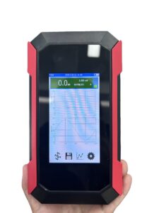
Click the image to know more about Wrindu Handheld PD Tester.
Why Can Electrical Noise Affect PD Measurements?
Partial discharge produces short electrical pulses. A PD measuring system detects these pulses and analyzes their characteristics.
The difficulty is that external interference can also produce electrical signals within the measurement bandwidth.
Common sources include:
- Switching operations in nearby equipment
- Poor grounding or bonding
- Electromagnetic interference from cables and instruments
- Corona or discharge activity around high voltage connections
- Noise introduced through the measurement circuit
The measuring system may display these signals even when they do not come from the insulation defect under investigation.
Therefore, a high PD reading does not automatically mean that the test object has an insulation problem.
How Can the High Voltage Source Introduce Interference?
The power source can affect the testing environment in several ways.
Corona Around High Voltage Connections
Corona may occur when the local electric field becomes strong enough to ionize the surrounding air.
Sharp metal edges, damaged insulation, loose connections, and unsuitable clearances can create local areas of high electric stress.
Corona can generate pulses that interfere with PD measurements.
Engineers should inspect high voltage terminals, connectors, exposed conductors, and nearby grounded structures before testing.
The test setup should follow the equipment manufacturer’s requirements for clearances and connection design.
Electrical Noise From Switching Circuits
Some high voltage systems use switching converters or electronic control circuits.
Their operation may introduce electrical noise through conducted or radiated coupling. Whether this affects the PD measurement depends on the source design, shielding, grounding, and measuring circuit.
Engineers should not assume that every switching power supply is unsuitable for PD testing. Instead, they should evaluate the complete system’s background noise under the intended test conditions.
Grounding and Measurement Connections
Incorrect grounding can create unwanted current paths and increase interference.
Long or poorly arranged measurement cables may also pick up electromagnetic signals.
A consistent grounding layout and suitable cable routing can help reduce these effects.
The grounding arrangement must still follow the equipment design and electrical safety requirements. Engineers should never disconnect protective earth connections as a noise-reduction method.
How Can Engineers Tell Real Partial Discharge From Interference?
One signal characteristic alone is rarely enough to identify the source of a PD reading.
Engineers should examine several factors together.
Check Whether the Signal Changes With Test Voltage
Some discharge activity starts only when the applied voltage reaches a particular level.
Engineers can record the signal as the voltage increases and decreases, provided the test procedure permits this.
If a signal repeatedly appears near a similar voltage level, it may provide useful diagnostic information. However, this behavior alone does not prove that the signal comes from an insulation defect.
Compare Measurements With the High Voltage Output Off
When the test procedure and equipment allow it, engineers can record the background signal before applying high voltage.
If the same interference remains with the source off, nearby equipment or the measurement system may be responsible.
Some noise sources operate only when the high voltage system is energized, so an off-state check cannot identify every problem.
Observe the Signal Pattern
A phase-resolved partial discharge (PRPD) pattern can help engineers study pulse distribution in relation to the AC voltage phase.
Different discharge sources may produce different patterns. However, patterns can overlap, and electrical interference may also appear in phase-related forms.
Engineers should combine pattern analysis with visual inspection, background measurements, and other diagnostic evidence.
How Can Engineers Reduce Background Noise During PD Testing?
Noise reduction should start with the physical test setup.
Prepare the Test Area
Remove unnecessary electrical equipment from the immediate test area where practical. Keep measurement cables away from power cables and switching equipment when the system layout permits.
Inspect connectors and high voltage terminals for contamination, damage, or poor contact.
Check Grounding and Shielding
Follow the test system’s grounding diagram. Use the specified shielded cables and connect shields according to the manufacturer’s instructions.
Avoid making extra grounding connections without understanding their effect on the measurement circuit.
Verify Background Noise Before Testing
Measure the background noise using the approved test procedure.
Record the test conditions, instrument settings, and observed interference. This provides a reference for later measurements.
A low background level is especially important when engineers need to detect small discharge signals.
Select a Suitable High Voltage Source
The source should support the required test voltage and provide a suitable electrical environment for the intended PD measurement.
Relevant factors include:
- Background noise under operating conditions
- Corona control in the high voltage circuit
- Output stability
- Compatibility with the PD measuring system
- Suitability for the test object and test standard
These properties should be confirmed for the complete test arrangement, not inferred from a product name alone.
Why Should Engineers Evaluate the Complete PD Test System?
A low-noise power source cannot correct every problem in a poorly arranged test circuit.
The final measurement depends on the source, high voltage connections, test object, coupling components, measuring instrument, cables, grounding, and surrounding environment.
For example, a well-designed source may still produce unreliable measurements if a high voltage connector generates corona or a measurement cable picks up nearby interference.
Engineers should therefore assess the complete setup before deciding whether a high PD reading comes from the test object.
How Does Wrindu Support High Voltage Testing?
Wrindu supplies high voltage testing equipment for electrical insulation and power equipment applications.
The RDVLF-Z80Y VLF AC Withstand Voltage Tester is designed for VLF cable withstand testing.
VLF withstand testing and partial discharge measurement are different test functions. Engineers who need PD measurements should confirm that the selected equipment and associated measuring system support the required PD test method.
FAQs About Power Sources and Partial Discharge Testing
Does every PD pulse indicate an insulation defect?
No. External interference, corona around test connections, and measurement-system noise can also produce pulses.
Can a stable high voltage output guarantee accurate PD measurements?
No. Output stability is useful, but background noise, grounding, shielding, and measurement-system performance also affect the results.
Why should engineers measure background noise before testing?
Background measurements help establish the noise level before the test voltage is applied. They provide a reference for evaluating later signals.
Can grounding problems cause false PD readings?
Yes. Poor grounding and unwanted current paths can introduce interference into the measurement circuit. Grounding must be checked against the system’s design.
Is VLF withstand testing the same as a PD test?
No. VLF withstand testing evaluates cable insulation under specified voltage conditions, while PD testing detects and analyzes partial discharge activity. Some systems support multiple test functions, but the functions should not be treated as interchangeable.
