

How Is Primary Injection Testing Used for Motor Protection?
Learn how primary injection testing checks motor protection relays, CT response, overload protection, earth fault detection, and trip circuits.
Motor protection systems prevent electrical motors from operating under abnormal conditions. Primary injection testing helps engineers check the current detection and protection response of motor feeder circuits.
The test applies current through a selected primary circuit. It can help verify current transformers (CTs), overcurrent protection, and associated trip circuits when the test arrangement supports these functions.
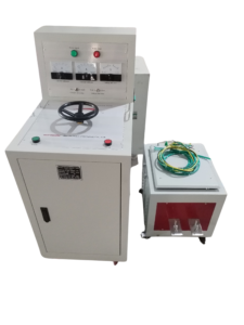
Click the image to know more about 6000A Primary Current Injection Tester.
What Protection Functions Are Used in Electrical Motor Systems?
Industrial motors use several protection functions to detect abnormal electrical and operating conditions.
Common motor protection functions include:
| Protection function | Purpose |
|---|---|
| Overload protection | Detect sustained current above the permitted operating level |
| Short-circuit protection | Detect excessive fault current |
| Earth fault protection | Detect current leakage to earth |
| Phase loss protection | Detect loss of one supply phase |
| Phase imbalance protection | Detect unequal phase currents |
| Locked rotor protection | Detect a motor that cannot accelerate or rotate normally |
Different motor protection relays support different functions. The actual protection configuration depends on motor ratings, operating conditions, and system design.
How Does Primary Injection Testing Check Motor Protection?
Primary injection testing sends current through the motor feeder’s primary circuit or associated CT primary conductor.
The injected current produces a corresponding CT secondary signal. The protection relay receives this signal and can be checked for its response to the applied current.
Depending on the test arrangement, engineers can verify:
- CT current detection.
- CT polarity and phase identification.
- Overcurrent relay pickup.
- Earth fault detection.
- Protection relay trip output.
- Associated circuit breaker trip operation.
The test current must be selected according to the CT ratio, relay settings, and approved testing procedure.
How Is Motor Overload Protection Tested?
Motor overload protection detects sustained excessive current that may cause motor overheating.
In a CT-based protection arrangement, engineers can inject current through the CT primary circuit and check whether the relay detects the corresponding current.
For a conventional thermal overload relay, primary current may be applied directly through its current-carrying elements if the manufacturer’s test procedure permits this arrangement.
The test should consider both the pickup level and the required operating characteristics.
A short primary injection test does not automatically verify the motor’s complete thermal protection model or reproduce actual motor heating conditions.
How Can Engineers Test Motor Overcurrent Protection?
Motor overcurrent protection detects current above a defined protection threshold.
Engineers can apply selected primary current values and check whether the protection relay responds according to its settings.
A typical test may include:
- Confirm the motor feeder CT ratio and relay settings.
- Identify the correct injection connection.
- Apply the selected test current.
- Monitor the relay’s current input.
- Record the pickup response.
- Check the trip output when included in the test.
For inverse-time protection, engineers should compare the measured operating time with the relay’s configured characteristic and applicable tolerances.
How Is Earth Fault Protection Tested in Motor Circuits?
Motor feeders may use phase CTs or a core balance current transformer to detect earth faults.
For a core balance CT arrangement, engineers can pass a test conductor through the CT aperture and return the conductor outside the aperture. This creates a residual current condition for checking the protection response.
For separate phase CT arrangements, the injection configuration must reproduce the intended residual current condition.
Engineers should record the applied current, relay pickup, operating time, and trip response where applicable.
The correct arrangement depends on the motor protection design and CT configuration.
What Is the Difference Between Primary Injection and Secondary Injection for Motor Protection?
Both methods can verify motor protection functions, but they use different test connections.
| Comparison | Primary injection | Secondary injection |
|---|---|---|
| Test connection | Primary current circuit | Relay secondary input |
| Current source | Primary current injection tester | Relay test set |
| CT response | Can verify CT response under primary current | Normally bypasses the CT primary path |
| Relay settings | Can check selected protection responses | Can test relay settings and characteristics directly |
| Wiring coverage | Can include selected primary and associated secondary paths | Focuses on secondary circuits |
| Main limitation | Requires suitable primary current and circuit access | Does not independently verify the complete primary current path |
Engineers may use both methods during motor protection commissioning. Primary injection checks the selected primary current path, while secondary injection supports more detailed relay function testing.
Which Equipment Is Used for Motor Protection Primary Injection Testing?
The equipment depends on the motor feeder design, CT ratio, protection settings, and required test current.
A primary current injection tester supplies current through the selected primary circuit.
For example, the Wrindu RDSL-82-6000D Primary Current Injection Tester has the following specifications:
| Parameter | Specification |
|---|---|
| Model | RDSL-82-6000D |
| Maximum output current | 6000 A |
| Rated capacity | 36 kVA |
| Output voltage | 6 V |
| Structure | Split-type |
| Current monitoring | Two ammeters |
| Power-on time | Less than 2.5 minutes |
| Working cycle | Longer than 10 minutes |
The required current for a motor protection test may be much lower than 6000 A. Engineers should select the injection level according to the motor feeder design and the test objective.
Explore the Wrindu RDSL-82-6000D Primary Current Injection Tester.
What Should Engineers Record During Motor Protection Testing?
Test records help engineers evaluate the motor protection system and compare results with its approved settings.
| Test item | Information to record |
|---|---|
| Motor information | Motor model and rated current |
| CT information | CT ratio and identification |
| Relay information | Relay model and protection settings |
| Injection current | Actual applied primary current |
| Pickup response | Current at which the relay operates |
| Operating time | Measured protection response time |
| Trip response | Trip output and breaker operation, when tested |
| Test conclusion | Result compared with applicable requirements |
The report should distinguish actual measurements from relay setting values and calculated results.
What Safety Precautions Are Required During Motor Protection Testing?
Motor protection testing requires the motor feeder to be placed in an approved test condition.
Engineers should confirm that the motor cannot start unexpectedly and that the test arrangement is isolated from normal operating power.
Important precautions include:
- Follow the motor and relay manufacturer’s instructions.
- Confirm the correct isolation and grounding arrangements.
- Check CT secondary circuit safety.
- Use suitable injection cables and connections.
- Confirm the permitted test current and duration.
- Keep personnel away from exposed energized test connections.
The test should be performed by qualified electrical personnel using an approved procedure.
When Should Engineers Perform Primary Injection Testing on Motor Protection Systems?
Primary injection testing may be included during motor feeder commissioning, protection system replacement, maintenance, and troubleshooting.
It is particularly useful when engineers need to check the installed primary current path and the response of associated CT-based protection circuits.
The test scope should be defined according to the motor protection design. Additional relay, insulation, winding, and functional tests may be required to assess the complete motor system.
