

How to Calibrate a Partial Discharge Measuring System?
Learn how PD calibration works, calculate injected charge, verify measuring system response, and check sensitivity before insulation testing.
A partial discharge measuring system must be checked before its results can be trusted. Engineers need to know whether the instrument can measure discharge signals correctly under the actual test conditions.
Calibration helps establish this relationship by injecting a known electrical charge into the measuring circuit and observing the instrument’s response.
This process is different from simply checking whether the instrument powers on or displays a signal. It verifies the measurement response of the test arrangement.
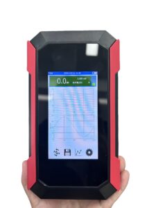
Click the image to know more about Wrindu Handheld PD Tester.
What Does Calibration Mean in Partial Discharge Testing?
In conventional electrical PD measurement, results are often expressed as apparent charge, measured in picocoulombs (pC).
A calibration device injects a known charge into the test circuit. The instrument response is then used to establish the relationship between the injected charge and the displayed measurement.
For example, an injected charge of 100 pC should produce the response expected from the system’s calibration procedure.
The actual response depends on the instrument settings and circuit configuration. Engineers should use the calibration method specified by the equipment manufacturer and applicable standard.
How Is the Calibration Charge Calculated?
A common calibration relationship is:
q₀ = C₀ × ΔU
Where:
- (q₀) = injected calibration charge in coulombs (C)
- (C₀) = calibration capacitor in farads (F)
- (\Delta U) = voltage step in volts (V)
For example, if a calibration capacitor has a capacitance of 10 pF and the applied voltage step is 10 V:
(q₀ = 10 \text{ pF} \times 10 \text{ V})
q₀ = 100 pC
This is an idealized calculation. Actual calibration equipment must account for its specified characteristics and operating procedure.
The example shows how a small capacitance and voltage step can produce a charge in the picocoulomb range.
Why Must Engineers Calibrate the Complete Test Circuit?
A PD instrument may respond differently when connected to different test circuits.
The test object’s capacitance, coupling capacitor, measuring impedance, and cable arrangement all affect the measurement response.
For this reason, calibration should be carried out with the test circuit arranged as required by the applicable procedure.
Calibrating the instrument separately from the test circuit may not verify the response of the complete measuring arrangement.
When Should Calibration Be Performed?
The required timing depends on the applicable standard, test procedure, and equipment instructions.
Engineers commonly need to verify calibration before making measurements. Calibration may also be required after changing the test circuit, replacing relevant components, or adjusting the measuring setup.
The exact procedure should follow the governing standard and manufacturer’s instructions rather than an assumed universal schedule.
What Is the Difference Between Calibration and Sensitivity?
These terms are related, but they do not mean the same thing.
Calibration establishes the relationship between a known injected charge and the measuring system’s response.
Sensitivity describes how well the system can detect small signals under the test conditions.
A system may respond correctly to a calibration pulse but still have limited ability to distinguish a small discharge signal from background interference.
Therefore, calibration alone does not prove that every small PD event can be detected.
How Can Engineers Check Whether the PD System Can Detect Small Signals?
Engineers should evaluate the measurement system under the conditions that will be used for the actual test.
Relevant checks include:
- Confirming the required measuring range
- Verifying the calibration response
- Checking the background noise level
- Confirming that the measuring cables and connections are correct
- Reviewing the detector’s specified performance
The acceptable detection level depends on the test object, the required measurement, and the applicable standard.
Engineers should not assume that every instrument has the same detection limit or that one sensitivity value applies to every circuit.
What Can Cause Calibration Results to Change?
A change in calibration response may indicate that the measuring arrangement has changed.
Possible causes include:
Changes to the Test Circuit
Replacing a coupling capacitor or measuring impedance can affect the circuit response.
After such changes, engineers should follow the required recalibration procedure.
Incorrect Instrument Settings
A different measuring range or configuration may change the displayed response.
Confirm that the settings match the calibration instructions before comparing results.
Connection Problems
Loose connectors, damaged cables, or incorrect connections may affect signal transfer.
Inspect the circuit according to the approved procedure before repeating the calibration.
Calibration Equipment Problems
The calibration device itself must be suitable for the required charge range and maintained according to its instructions.
If its output is uncertain, the calibration result may not provide a reliable reference.
How Should Engineers Record Calibration Results?
Calibration records help engineers compare measurements over time and identify changes in the test arrangement.
A useful record can include:
| Record item | Purpose |
|---|---|
| Test object identification | Identifies the equipment under test |
| Measuring system model | Records the instrument used |
| Circuit configuration | Documents the connected components |
| Injected calibration charge | Records the reference charge |
| Instrument response | Shows the observed result |
| Date and operator | Supports traceability |
| Relevant settings | Helps reproduce the measurement |
The record should follow the laboratory’s quality system and applicable testing requirements.
Why Is Calibration Important for Routine Quality Control?
In manufacturing and laboratory testing, measurement results may be compared across products, production batches, or test dates.
If the measuring system’s response changes without being identified, differences in recorded PD values may be difficult to interpret.
Regular calibration checks help maintain measurement consistency and support reliable quality-control decisions.
However, a calibrated measuring system cannot by itself establish that a product passes every insulation requirement. Engineers must also interpret the results against the relevant acceptance criteria.
FAQs About Partial Discharge Calibration
What unit is used for apparent charge in PD testing?
Apparent charge is commonly expressed in picocoulombs (pC), although the applicable measurement range depends on the test and instrument.
Does calibration remove electrical noise?
No. Calibration establishes the measurement response to a known charge. Background noise must be evaluated separately.
Should calibration be repeated after changing the test circuit?
Follow the applicable standard and manufacturer’s instructions. Changes to components or connections may require calibration to be checked again.
Does a calibrated instrument guarantee detection of every PD event?
No. Detection also depends on the circuit response, background noise, instrument performance, and characteristics of the discharge signal.
Why should calibration results be recorded?
Records support traceability, help reproduce test conditions, and make it easier to identify changes in the measuring system.
