

How to Set Up a Partial Discharge Test Circuit?
Learn how a PD test circuit works, including the high voltage source, coupling capacitor, measuring impedance, detector, and calibration device.
Partial discharge (PD) testing depends on more than a high voltage source. The test circuit must also transfer discharge signals to the measuring instrument so that engineers can detect and evaluate them.
A poorly arranged circuit may reduce measurement sensitivity or make test results difficult to interpret. Understanding the role of each component helps engineers prepare a suitable test setup before applying high voltage.
This article explains the main components of a conventional electrical partial discharge test circuit and how they work together.
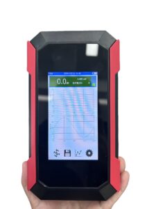
Click the image to know more about Wrindu Handheld PD Tester.
What Are the Main Components of a PD Test Circuit?
A conventional PD test circuit usually includes a high voltage source, a test object, a coupling capacitor, a measuring impedance, and a PD measuring instrument.
Each component has a specific role.
| Component | Main function |
|---|---|
| High voltage source | Applies the required test voltage |
| Test object | The insulation or electrical equipment under evaluation |
| Coupling capacitor | Provides a path for detecting high-frequency discharge pulses |
| Measuring impedance | Converts the measured pulse current into a signal for the detector |
| PD measuring instrument | Displays and analyzes the detected signals |
| Calibration device | Injects a known charge for measurement calibration |
The exact circuit depends on the test method, equipment design, and applicable standard. Some systems use different coupling arrangements or integrated measuring units.
How Does the High Voltage Source Connect to the Test Object?
The high voltage source applies the specified voltage to the test object.
For example, during a transformer insulation test, the source may energize a winding while the other connections follow the approved test circuit.
The test arrangement must match the equipment under test. A cable, transformer, and switchgear assembly do not necessarily use the same connection method.
Before energizing the circuit, engineers should confirm:
- The correct test terminals
- The required grounding connections
- The rated voltage of each component
- The specified clearances and insulation requirements
- The permitted connection sequence
The test circuit should be assembled according to the equipment manuals and the applicable test procedure.
What Does a Coupling Capacitor Do in PD Testing?
A coupling capacitor is an important component in many conventional PD measuring circuits.
It provides a path through which fast discharge pulses can reach the measuring circuit while helping separate the measurement path from the main high voltage supply.
The coupling capacitor must be suitable for the test voltage and the intended measuring arrangement.
Its capacitance also affects the electrical behavior of the complete circuit. Engineers should therefore use the specified component values rather than selecting a coupling capacitor based on voltage rating alone.
How Does the Coupling Capacitor Affect Measurement?
The coupling capacitor and the test object’s capacitance influence the distribution of pulse signals in the circuit.
If the components are poorly matched to the measuring system, the detected signal may become weaker or the circuit response may change.
This does not mean that a larger coupling capacitor is always better. The appropriate value depends on the test object, measuring impedance, frequency response, and circuit design.
Engineers should follow the measuring system manufacturer’s recommendations.
What Is the Function of Measuring Impedance?
Measuring impedance, sometimes called a measuring impedance or detection impedance, helps convert discharge pulse current into a measurable voltage signal.
The PD instrument then processes this signal to display relevant measurement information.
The measuring impedance must be compatible with the detector and the rest of the circuit.
Incorrect connections, unsuitable components, or poor cable arrangements can change the measured response. For this reason, engineers should use the specified impedance and connection layout.
How Should Engineers Connect the PD Measuring Instrument?
The measuring instrument receives signals from the measurement circuit and presents them for analysis.
Depending on the instrument, the displayed information may include apparent charge, pulse magnitude, pulse count, and phase-resolved patterns.
Engineers should check the following before testing:
- Confirm that the detector is connected to the correct measuring port.
- Check that the measuring impedance matches the circuit design.
- Use the specified measuring cables and connectors.
- Confirm the instrument settings and measurement range.
- Verify the circuit with the approved calibration procedure.
The instrument’s display should not be treated as proof that every detected pulse comes from the insulation under test. Signal interpretation still requires suitable test conditions and technical judgment.
Why Does Test Circuit Layout Matter?
The physical arrangement can affect the performance of the complete measurement system.
For example, an unsuitable cable route may increase electromagnetic coupling. Poorly designed high voltage connections may also introduce unwanted discharge activity.
Engineers should keep the circuit organized and follow the manufacturer’s recommended layout.
The goal is not simply to reduce the number of components. It is to create a test circuit in which each component performs its intended function and the detector can measure discharge signals reliably.
What Should Engineers Check Before Energizing the Circuit?
A pre-test inspection helps identify connection problems before high voltage is applied.
Check that:
- All components are rated for the intended test conditions.
- Connections match the approved circuit diagram.
- Grounding and protective measures are in place.
- The test area is secured.
- The measuring instrument is configured correctly.
- Calibration equipment is available where required.
High voltage testing should be performed only by qualified personnel using the approved safety procedure.
FAQs About Partial Discharge Test Circuits
Is a coupling capacitor required for every PD test?
No. Many conventional electrical PD measurement systems use a coupling capacitor, but the required arrangement depends on the measurement method and instrument design.
Can engineers use any measuring impedance?
No. The measuring impedance must be compatible with the circuit and PD detector. An unsuitable component may change the measurement response.
Why is the calibration device connected to the test circuit?
A calibration device injects a known charge into the measuring circuit. This helps verify the relationship between the injected charge and the instrument’s response.
Does the high voltage source measure partial discharge by itself?
Not necessarily. A high voltage source supplies the test voltage, while a compatible PD measuring system detects and evaluates discharge signals. Some integrated systems combine multiple functions.
Should every electrical product use the same PD test circuit?
No. The circuit depends on the test object, voltage requirements, measurement method, and applicable test standard.
