

How to Measure Harmonics in a Three-Phase Power System?
Learn how to measure voltage and current harmonics in three-phase systems, calculate THD, analyze test results, and reduce harmonic distortion.
Harmonics are common in three-phase electrical systems, especially in factories that use variable frequency drives, welding machines, rectifiers, and other nonlinear loads.
High harmonic levels can cause transformer overheating, motor losses, cable heating, and unexpected equipment problems. Measuring voltage and current harmonics helps engineers identify distortion and check whether the electrical system operates normally.
This article explains how to measure harmonics in a three-phase power system, what instruments are needed, and how to understand the test results.
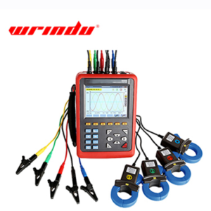
Click the image to know more about Wrindu Power Quality Analyzer.
What Are Harmonics in a Three-Phase Power System?
Harmonics are voltage or current components with frequencies that are integer multiples of the fundamental frequency.
For a 50 Hz power system:
| Harmonic Order | Frequency |
|---|---|
| 1st | 50 Hz |
| 2nd | 100 Hz |
| 3rd | 150 Hz |
| 5th | 250 Hz |
| 7th | 350 Hz |
| 11th | 550 Hz |
| 13th | 650 Hz |
The fundamental frequency is the normal operating frequency of the power system. Harmonic components appear when the voltage or current waveform is distorted.
In three-phase systems, engineers usually check both voltage harmonics and current harmonics because they provide different information about the electrical network.
What Causes Harmonics in Three-Phase Systems?
Harmonics mainly come from nonlinear electrical loads. These loads draw current in a non-sinusoidal waveform, even when the supply voltage is relatively stable.
Common sources include:
1. Variable Frequency Drives
Variable frequency drives (VFDs) control motor speed by converting AC power into DC and then back into AC.
Their rectifier circuits can draw distorted current from the supply, producing harmonic components.
2. Industrial Rectifiers
Rectifiers convert AC power into DC power. They are widely used in battery charging systems, electroplating equipment, and industrial power supplies.
Their switching and conversion processes can introduce current harmonics.
3. Welding Machines
Industrial welding machines often draw fluctuating and nonlinear currents. When several welding machines operate on the same electrical network, harmonic distortion may increase.
4. Switching Power Supplies and LED Lighting
Electronic power supplies and LED drivers use power conversion circuits. Poorly designed or inadequately filtered equipment may generate significant current harmonics.
5. UPS Systems
Uninterruptible power supplies use power electronic converters. Depending on their design and operating conditions, they may contribute to harmonic distortion.
What Is the Difference Between Voltage Harmonics and Current Harmonics?
Voltage harmonics and current harmonics are related, but they are not the same.
| Comparison | Voltage Harmonics | Current Harmonics |
|---|---|---|
| Meaning | Harmonic distortion in voltage | Harmonic distortion in current |
| Common Causes | Harmonic currents flowing through system impedance, distorted supply voltage | Nonlinear electrical loads |
| Main Effects | Distorted supply voltage and equipment stress | Additional heating and losses |
| Measurement Point | Voltage test terminals | Current clamps or sensors |
| Main Indicator | Voltage THD | Current THD |
Current harmonics can flow through cables, transformers, and other equipment. Because electrical networks have impedance, these currents can also create voltage distortion.
Measuring both values helps engineers understand how harmonic distortion affects the system.
What Equipment Is Needed to Measure Three-Phase Harmonics?
A power quality analyzer is commonly used for harmonic testing in three-phase electrical systems.
The basic equipment includes:
- Power quality analyzer: Measures voltage, current, harmonics, and THD.
- Voltage test leads: Connect to the three phases and neutral point.
- Current clamps: Measure current in each phase.
- Test accessories: Provide suitable connections for the selected measurement range.
When selecting an analyzer, check the number of measurement channels, harmonic measurement range, current sensor capacity, and data recording functions.
For three-phase systems with neutral conductors, four voltage channels and four current channels can provide a more complete measurement setup.
How to Measure Harmonics in a Three-Phase Power System?
Follow these steps to measure voltage and current harmonics.
Step 1: Check the Electrical System
Before testing, identify the system voltage, nominal frequency, wiring configuration, and connected loads.
Check whether the system is a three-phase three-wire or three-phase four-wire system. Select the correct measurement mode on the analyzer.
Step 2: Connect the Voltage Test Leads
Connect the voltage leads to the corresponding phase terminals.
For a three-phase four-wire system, connect the neutral lead as required by the instrument’s wiring diagram.
Make sure the phase sequence and connections are correct.
Step 3: Install the Current Clamps
Place one current clamp around each phase conductor.
Check the direction of each clamp and match its channel with the corresponding voltage phase. Incorrect phase matching can lead to inaccurate power measurements and incorrect analysis.
If neutral current is also required, use an additional current channel.
Step 4: Start the Measurement
Turn on the analyzer and check the basic readings:
- Phase voltage
- Phase current
- Frequency
- Active and reactive power
- Power factor
Confirm that the readings are reasonable before reviewing harmonic data.
Step 5: Check the Harmonic Spectrum
Open the harmonic analysis screen.
The analyzer should display the individual harmonic components for each phase. Engineers can compare the harmonic levels and identify which orders contribute most to waveform distortion.
For example, the 5th and 7th harmonics are often found in systems with six-pulse rectifier loads.
Step 6: Check Total Harmonic Distortion
Review voltage THD and current THD for each phase.
Compare the results with the applicable power quality requirements. If one phase has significantly higher distortion than the others, investigate its connected loads and electrical connections.
Step 7: Record and Analyze the Results
Save the measurement data for further analysis.
For systems with changing loads, continuous recording can help identify when harmonic levels increase and which equipment is operating at that time.
How to Calculate Total Harmonic Distortion (THD)?
Total harmonic distortion (THD) describes the combined effect of harmonic components compared with the fundamental component.
The voltage THD formula is:
[THD_V=\frac{\sqrt{V_2^2+V_3^2+\cdots+V_n^2}}{V_1}\times100%]

The current THD formula is:
[
THD_I=\frac{\sqrt{I_2^2+I_3^2+\cdots+I_n^2}}{I_1}\times100%
]

Where:
- (V_1) = Fundamental voltage
- (V_2,V_3,\ldots,V_n) = Individual harmonic voltages
- (I_1) = Fundamental current
- (I_2,I_3,\ldots,I_n) = Individual harmonic currents
For example, if the fundamental voltage is 230 V and the combined RMS value of the measured harmonic voltage components is 11.5 V:
[
THD_V=\frac{11.5}{230}\times100%=5%
]

The voltage THD is 5%.
THD is useful for comparing waveform distortion, but engineers should also check individual harmonic orders to understand which frequencies contribute most to the distortion.
How to Interpret Harmonic Measurement Results?
The test results help engineers identify possible harmonic sources and their effects.
| Test Result | Possible Meaning | Recommended Check |
|---|---|---|
| High 3rd Harmonic Current | Nonlinear single-phase loads or triplen harmonic accumulation | Check neutral current and single-phase loads |
| High 5th Harmonic Current | Commonly associated with six-pulse rectifiers and drives | Check VFDs and rectifier loads |
| High 7th Harmonic Current | May be associated with converter loads | Check industrial power converters |
| High Voltage THD | Distorted supply voltage | Check network impedance and harmonic sources |
| High Current THD | Distorted load current | Identify nonlinear loads |
| Large Differences Between Phases | Uneven loads or different harmonic sources | Compare phase loading and connected equipment |
These patterns are useful clues, not definitive fault diagnoses. Engineers should consider the system configuration, load conditions, and measurement location before identifying the source.
How to Reduce Harmonics in Three-Phase Systems?
The correct solution depends on the harmonic source and the severity of distortion.
Common methods include:
- Passive harmonic filters: Use selected inductors and capacitors to reduce specific harmonic components.
- Active harmonic filters: Detect harmonic currents and inject compensating currents.
- Line reactors: Help reduce harmonic current from certain drive and rectifier systems.
- Low-harmonic drives: Use drive designs that produce lower harmonic distortion.
- Load distribution: Review the connection and distribution of nonlinear loads across the electrical system.
Before installing filters or other corrective equipment, engineers should measure the harmonic spectrum and evaluate the network conditions.
Which Power Quality Analyzer Can Measure Three-Phase Harmonics?
The Wrindu RDCR5000 Digital Power Quality Analyzer supports simultaneous measurement of four voltage channels and four current channels.
Its harmonic analysis functions cover the 0th to 50th order and include voltage and current THD measurement for each phase.
Other functions include:
- Real-time voltage and current waveforms
- Harmonic ratio bar charts
- Three-phase imbalance measurement
- Voltage flicker measurement
- Transient waveform capture
- Long-term trend recording
The instrument can record 20 selected parameters simultaneously at five-second intervals, with a maximum recording period of 300 days under the specified configuration.
These functions allow engineers to compare harmonic levels between phases and monitor changes under different load conditions.
Frequently Asked Questions
What is the most common harmonic order in three-phase systems?
The 5th and 7th harmonics are common in systems with six-pulse rectifiers and variable frequency drives. The actual harmonic spectrum depends on the load and system configuration.
Why should engineers measure both voltage and current harmonics?
Current harmonics help identify distortion produced by connected loads. Voltage harmonics show how that distortion affects the supply voltage. Measuring both provides a clearer view of system conditions.
Can a multimeter measure harmonics?
Most standard multimeters cannot provide detailed harmonic analysis. A power quality analyzer or harmonic analyzer is needed to measure individual harmonic components and THD.
What is an acceptable THD value?
Acceptable THD limits depend on the applicable standard, voltage level, measurement point, and electrical system. Engineers should refer to the relevant requirements, such as IEEE 519 or applicable IEC standards, rather than use one value for every installation.
How often should harmonic testing be performed?
Testing frequency depends on the equipment and operating conditions. It is useful to measure after installing large nonlinear loads, when electrical problems occur, and during scheduled maintenance.
Conclusion
Measuring harmonics in a three-phase power system helps engineers identify waveform distortion and understand its impact on electrical equipment.
A power quality analyzer can measure individual voltage and current harmonics, calculate THD, and record changes over time. By checking all three phases and reviewing the harmonic spectrum, engineers can locate possible sources and choose suitable corrective measures.
