

What Is the Difference Between TDR and ARM Cable Fault Location?
Compare TDR and ARM cable fault location methods. Learn how they work, which cable faults they detect, and when to use each method.
TDR and ARM are two methods used to locate faults in underground power cables. Both use electrical pulse reflection to estimate the distance to a fault, but they work under different test conditions.
TDR uses low-voltage pulses and is suitable for many open-circuit and low-resistance faults. ARM, or Arc Reflection Method, uses a high-voltage surge to create an arc at a high-resistance fault. It then analyzes the reflected signal to estimate the fault distance.
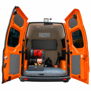
Click the image to know more about Wrindu RDCD-C Vehicle-Mounted Cable Fault Testing System.
What Is TDR Cable Fault Location?
TDR stands for Time Domain Reflectometry. It sends a low-voltage electrical pulse into a cable and records the signal reflected by an impedance change.
When the pulse reaches an open circuit, short circuit, or other impedance variation, part of the signal returns to the testing instrument. The instrument measures the round-trip time and calculates the distance to the reflection point.
The basic distance formula is:
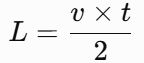
[
L=\frac{v\times t}{2}
]
Where:
- L: Distance from the test end to the reflection point
- v: Pulse propagation velocity in the cable
- t: Total round-trip travel time
TDR is commonly used for cable length measurement and fault pre-location. However, a low-voltage pulse may not produce a clear reflection from some high-resistance faults.
What Is ARM Cable Fault Location?
ARM stands for Arc Reflection Method. It is designed to help locate high-resistance cable faults that are difficult to detect with ordinary low-voltage TDR.
During an ARM test, a high-voltage surge is applied to the cable. When the voltage is high enough, the insulation at a suitable fault point breaks down temporarily and forms an arc.
The testing instrument sends a low-voltage measuring pulse while the arc is present. The arc changes the electrical condition at the fault point, allowing the instrument to capture a reflection that can be analyzed to estimate the fault distance.
ARM combines high-voltage breakdown and low-voltage reflection measurement. It is especially useful for certain high-resistance faults.
How Do TDR and ARM Work Differently?
The main difference is the condition under which the instrument measures the reflected signal.
| Comparison | TDR | ARM |
|---|---|---|
| Full name | Time Domain Reflectometry | Arc Reflection Method |
| Test signal | Low-voltage pulse | High-voltage surge combined with a measuring pulse |
| Working principle | Reflection caused by impedance changes | Reflection measured while an arc forms at the fault |
| Main application | Cable length measurement and fault pre-location | Pre-location of suitable high-resistance faults |
| Fault condition | Fault creates a detectable impedance change | Fault needs to break down and form an arc under the applied surge |
| Test equipment | TDR cable fault locator | Cable fault locator with ARM function and a suitable high-voltage generator |
| Test voltage | Low voltage | High voltage is used to create the arc |
TDR is usually the first method to try when a cable fault produces a clear reflection. ARM is useful when a high-resistance fault cannot be identified clearly with ordinary TDR.
Which Cable Faults Can TDR and ARM Detect?
Different fault types produce different electrical responses. Choosing the right method depends on the fault resistance and whether the fault can create a clear reflection or an arc.
| Fault type | TDR | ARM |
|---|---|---|
| Open-circuit fault | Suitable | Usually unnecessary |
| Short-circuit fault | Suitable | Usually unnecessary |
| Low-resistance fault | Often suitable | Usually unnecessary |
| High-resistance fault | May be difficult | Suitable if the fault can form an arc |
| Intermittent fault | Depends on the fault condition | May help if the fault produces a repeatable arc response |
ARM does not guarantee detection of every high-resistance fault. The fault must respond to the applied surge, and the cable insulation and test conditions must allow a suitable measurement.
What Are the Advantages and Limitations of TDR and ARM?
Each method has its own strengths and limitations.
| Method | Advantages | Limitations |
|---|---|---|
| TDR | Fast measurement, low-voltage testing, useful for cable length and many common faults | May not show a clear reflection from high-resistance faults |
| ARM | Helps locate certain high-resistance faults by creating an arc at the fault point | Requires high-voltage equipment and suitable fault breakdown conditions |
TDR is generally simpler for initial cable testing. ARM adds another option when low-voltage reflection is not enough to identify the fault distance.
Technicians should select the method according to the cable condition and the test instrument’s available functions.
Can TDR and ARM Be Used in the Same Cable Fault Testing System?
Yes. Some cable fault testing systems combine TDR and ARM functions with high-voltage surge testing and acoustic-magnetic pinpointing.
A typical cable fault location process may include:
- Cable length measurement: Use TDR to measure the cable length and check the waveform.
- Fault pre-location: Select TDR or ARM according to the fault type and reflection response.
- High-voltage testing: Apply a suitable surge when the selected method requires it.
- Ground pinpointing: Use an acoustic-magnetic locator to find the fault position on the ground.
- Cable route detection: Trace the underground cable route before excavation.
Combining these methods helps technicians handle different fault conditions without relying on a single test method.
How Do You Choose Between TDR and ARM?
The choice depends mainly on the fault resistance and the test result.
| Testing situation | Recommended method |
|---|---|
| Cable length measurement | TDR |
| Clear open-circuit fault | TDR |
| Clear low-resistance fault | TDR |
| High-resistance fault with no clear TDR reflection | Consider ARM |
| Fault can form an arc under a high-voltage surge | ARM may be suitable |
| Exact fault position needs confirmation | Use a suitable ground pinpointing method |
Before testing, technicians should check the cable type, rated voltage, insulation condition, and instrument specifications. High-voltage testing must follow the equipment manufacturer’s safety procedures.
Frequently Asked Questions About TDR and ARM
Is ARM better than TDR for cable fault location?
Neither method is suitable for every fault. TDR works well for many open-circuit and low-resistance faults, while ARM is designed to help locate certain high-resistance faults.
Does ARM use high voltage?
Yes. ARM uses a high-voltage surge to create a temporary arc at a suitable fault point. A measuring pulse is then used to analyze the reflected signal.
Can TDR detect high-resistance cable faults?
Sometimes, but the reflected signal may be too weak to identify clearly. ARM or another suitable high-voltage pre-location method may be needed.
What is the difference between ARM and the Multiple Impulse Method?
ARM uses a high-voltage surge to create an arc and measures the reflection during the arc. The Multiple Impulse Method uses multiple impulse signals to help compare or identify fault reflections. They are different methods and should not be treated as interchangeable.
Do TDR and ARM locate the exact position for excavation?
No. Both methods mainly estimate the fault distance along the cable. Technicians usually need a separate acoustic-magnetic pinpointing method to find the exact position on the ground.
Can one cable fault locator support both TDR and ARM?
Some integrated cable fault location systems support both methods. Buyers should check the instrument’s actual functions and supported test modes before purchasing.
About Wrindu Cable Fault Testing Equipment
Wrindu is a Chinese OEM manufacturer of electrical testing equipment and power testing solutions. Its cable testing product range supports cable length measurement, fault pre-location, high-voltage testing, ground pinpointing, and cable route detection.
The RDCD-C Vehicle-Mounted Cable Fault Testing System integrates different modules for field cable fault diagnosis. Its configuration includes cable fault pre-location, high-voltage testing, acoustic-magnetic pinpointing, and cable path detection.
For detailed functions and specifications, visit the RDCD-C Vehicle-Mounted Cable Fault Testing System product page.
