

How Does Time Domain Reflectometry (TDR) Work in Cable Fault Location?
Learn how TDR works in cable fault location, how to calculate fault distance, what faults it can detect, and its advantages and limitations.
Time Domain Reflectometry (TDR) is a common method for locating faults in underground power cables. It sends a low-voltage electrical pulse into a cable and measures the reflected signal.
By analyzing the time and shape of the reflected pulse, a TDR cable fault locator can estimate the distance to a fault. This method is useful for detecting cable breaks, short circuits, and low-resistance faults.

Click the image to know more about Wrindu RDCD-C Vehicle-Mounted Cable Fault Testing System.
What Is Time Domain Reflectometry in Cable Testing?
Time Domain Reflectometry is a cable testing method based on electrical pulse reflection.
When a pulse travels through a cable, it normally moves along the cable with a stable propagation speed. If it reaches a point where the cable impedance changes, part of the pulse reflects toward the testing instrument.
The instrument displays the transmitted and reflected signals as a waveform. Technicians can use the waveform to identify the reflection point and estimate its distance from the test end.
TDR is mainly used for cable length measurement and fault pre-location. It does not usually identify the exact fault position on the ground.
How Does a TDR Cable Fault Locator Work?
A TDR instrument locates a cable fault through four basic steps:
- Send an electrical pulse: The instrument sends a low-voltage pulse into the cable.
- Receive the reflected signal: The pulse reflects when it reaches a fault or an impedance change.
- Measure the travel time: The instrument records the time between pulse transmission and signal reception.
- Calculate the distance: The instrument uses the pulse travel time and cable propagation velocity to estimate the distance to the reflection point.
The result is usually shown as a waveform with a horizontal distance scale. A change in the waveform may indicate a cable fault, joint, branch, or other impedance variation.
How Do You Calculate Cable Fault Distance Using TDR?
A TDR instrument calculates the fault distance using the following formula:
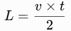
[
L=\frac{v\times t}{2}
]
Where:
| Symbol | Meaning | Unit |
|---|---|---|
| L | Distance from the test end to the reflection point | m |
| v | Pulse propagation velocity in the cable | m/μs |
| t | Total round-trip travel time of the pulse | μs |
The formula divides the total travel distance by two because the pulse travels to the reflection point and then returns to the instrument.
Example:
Assume that:
- Pulse propagation velocity: 160 m/μs
- Round-trip travel time: 10 μs
The calculated distance is:
[
L=\frac{160\times10}{2}=800m
]
The reflection point is approximately 800 meters from the test end.
The result depends on the accuracy of the propagation velocity setting. Different cable materials and structures can have different propagation velocities, so technicians should use the correct cable parameters.
What Types of Cable Faults Can TDR Detect?
TDR can detect faults that create a clear change in cable impedance. Its performance depends on the fault type, cable structure, and signal reflection strength.
| Cable condition | TDR response | Detection notes |
|---|---|---|
| Open-circuit fault | Usually a clear positive reflection | The pulse reflects strongly at the broken end |
| Short-circuit fault | Usually a negative reflection | The short circuit changes the cable impedance |
| Low-resistance fault | Often produces a visible reflection | Detection depends on the resistance and fault location |
| High-resistance fault | May produce a weak or unclear reflection | A separate high-voltage method may be needed |
| Cable joint or branch | May create a waveform change | The waveform needs to be interpreted carefully |
TDR works well for many open-circuit and low-resistance faults. However, some high-resistance faults do not produce a clear reflection under low-voltage testing conditions.
For these faults, technicians may need a high-voltage surge method or another suitable pre-location technique.
What Does a TDR Waveform Show?
A TDR waveform shows how the electrical pulse changes as it travels through the cable.
Technicians usually examine three main features:
- Reflection direction: The waveform may rise or fall depending on the type of impedance change.
- Reflection amplitude: A stronger reflection may indicate a more significant impedance difference.
- Reflection time: The time between pulse transmission and reception helps calculate the distance.
A waveform does not always provide a direct fault diagnosis. Cable joints, branches, changes in cable type, and other impedance variations can also produce reflections.
Technicians should compare the waveform with cable information and test results before deciding where the fault is located.
What Are the Advantages and Limitations of TDR?
TDR is useful for cable testing because it provides fast distance estimation without requiring a high-voltage breakdown test for every measurement.
| Advantages | Limitations |
|---|---|
| Uses low-voltage test pulses | May not detect some high-resistance faults |
| Measures cable length | Requires a suitable propagation velocity setting |
| Estimates the distance to a reflection point | Cannot always distinguish a fault from a cable joint or branch |
| Provides a waveform for analysis | Does not directly identify the exact ground position |
| Supports cable fault pre-location | May require other methods for complex faults |
TDR is often the first step in cable fault pre-location. If the waveform does not show a clear fault reflection, technicians can select another method based on the fault characteristics.
What Is the Difference Between TDR and High-Voltage Surge Testing?
TDR and high-voltage surge testing use different signal conditions and serve different purposes.
| Comparison | TDR | High-Voltage Surge Testing |
|---|---|---|
| Test signal | Low-voltage electrical pulse | High-voltage impulse |
| Main principle | Signal reflection | Insulation breakdown and discharge |
| Main purpose | Cable length measurement and fault pre-location | Pre-location of suitable high-resistance faults and fault pinpointing |
| Suitable faults | Open circuits and many low-resistance faults | Certain high-resistance and intermittent faults |
| Ground pinpointing | Not usually used alone | Can work with acoustic and magnetic detection |
TDR is suitable when the fault creates a clear impedance change. High-voltage surge testing is useful when a high-resistance fault cannot be located clearly with a low-voltage pulse.
These methods can work together in a complete cable fault location process.
How Is TDR Used in an Underground Cable Fault Location System?
In an underground cable fault location system, TDR is generally used for the initial distance measurement.
A typical workflow includes:
- Confirm the cable information and isolate the cable from the power supply.
- Connect the TDR instrument to the cable under test.
- Set the correct propagation velocity.
- Send a pulse and analyze the reflected waveform.
- Estimate the fault distance from the test end.
- Select a suitable pinpointing method if the fault location needs further confirmation.
After pre-location, technicians may use an acoustic and magnetic cable fault locator to find the fault position on the ground. A cable path detector can also help trace the cable route before excavation.
For a vehicle-mounted cable fault testing system, TDR can be one part of a larger testing setup that combines pre-location, high-voltage testing, ground pinpointing, and cable route detection.
Frequently Asked Questions About TDR Cable Fault Location
Can TDR locate underground cable faults?
Yes. TDR can estimate the distance from the test end to an underground cable fault by measuring the reflected pulse. Additional pinpointing equipment may be needed to identify the exact position on the ground.
Can TDR detect high-resistance cable faults?
Some high-resistance faults produce weak reflections that are difficult to identify with low-voltage TDR. High-voltage surge or other suitable methods may be needed.
Why is the TDR distance divided by two?
The pulse travels from the test instrument to the reflection point and then returns. The measured time represents this round trip, so the calculated distance is divided by two.
Does TDR show the exact cable fault position?
No. TDR estimates the distance along the cable. Ground pinpointing is usually required to identify the exact excavation position.
What affects TDR measurement accuracy?
Propagation velocity settings, cable type, cable structure, waveform interpretation, and the strength of the reflected signal can all affect the result.
Can TDR measure cable length?
Yes. When the cable end produces a clear reflection, TDR can estimate the total cable length based on the pulse travel time and propagation velocity.
About Wrindu Cable Fault Testing Equipment
Wrindu is a Chinese OEM manufacturer of electrical testing equipment and power testing solutions. Its cable fault testing equipment supports cable length measurement, fault pre-location, high-voltage testing, ground pinpointing, and cable route detection.
The RDCD-C Vehicle-Mounted Cable Fault Testing System combines different testing modules for field cable fault diagnosis. It is designed for power utilities, cable maintenance teams, and other users who need an integrated cable testing setup.
The system is supplied without a vehicle. Customers can select a suitable vehicle and arrange installation according to their field requirements.
For more information, visit the RDCD-C Vehicle-Mounted Cable Fault Testing System product page.
