

Why Does a CT Secondary Circuit Show No Current During Primary Injection Testing?
Learn why a CT secondary circuit shows no current during primary injection testing, including open circuits, wiring faults, measurement errors, and safety checks.
During primary current injection testing, engineers may find that the current transformer (CT) secondary circuit shows no current even though primary current is flowing.
This problem may result from an open secondary circuit, incorrect wiring, a disconnected measuring instrument, or an unsuitable test connection. Engineers should check the CT secondary circuit before concluding that the CT is defective.
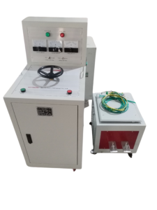
Click the image to know more about 6000A Primary Current Injection Tester.
How Should CT Secondary Current Respond During Primary Injection Testing?
A current transformer converts primary current into a proportional secondary current according to its transformation ratio.
For an ideal CT, the relationship is:
[
I_s=\frac{I_p}{K}
]
Where:
- Is = secondary current (A)
- Ip = primary current (A)
- K = CT transformation ratio
For example, a CT with a ratio of 1000/5 A has a nominal ratio of 200:1. When the primary current is 1000 A, the corresponding secondary current is 5 A under ideal conditions.
Actual measurements may differ because of CT accuracy characteristics, burden, saturation, and test conditions.
Why Is There No Secondary Current When Primary Current Is Applied?
Several problems can interrupt the secondary current measurement.
| Possible cause | What happens | Recommended inspection |
|---|---|---|
| Open secondary circuit | Secondary current cannot flow through the intended circuit | Check circuit continuity under safe conditions |
| Loose terminal | Electrical connection becomes intermittent | Inspect terminal connections |
| Incorrect wiring | Measuring instrument is connected to the wrong terminals | Compare wiring with the CT diagram |
| Open test lead | Measuring circuit is incomplete | Inspect test leads and connectors |
| Incorrect instrument connection | Current is not measured through the intended path | Check meter connection and range |
| Incorrect CT configuration | The selected conductor does not produce the expected CT response | Check conductor routing and CT arrangement |
An open CT secondary circuit is a serious safety concern when primary current is flowing. Never disconnect or open a CT secondary circuit under energized primary-current conditions.
How Can Engineers Check CT Secondary Circuit Continuity?
Engineers should first establish a safe test condition according to the approved CT isolation and shorting procedure.
The secondary circuit can then be inspected for open connections, incorrect terminal arrangements, damaged wires, and disconnected measuring instruments.
A practical inspection sequence includes:
- Identify the CT secondary terminals.
- Check the approved secondary wiring diagram.
- Inspect terminal blocks and shorting links.
- Check the measuring circuit and test leads.
- Verify that the measuring instrument is connected correctly.
- Confirm circuit continuity using an approved method under safe conditions.
Do not perform resistance or continuity measurements on an energized CT secondary circuit.
Can Incorrect CT Wiring Cause a Zero Current Reading?
Yes. Incorrect terminal connections can prevent the measuring instrument from detecting the expected secondary current.
For example, the meter may be connected to an incorrect terminal pair or the test circuit may bypass the intended measurement point.
Engineers should compare the actual wiring with the CT terminal markings and approved drawings. They should also confirm the correct current measurement range and instrument connection method.
Can CT Saturation Affect Secondary Current Measurements?
Yes. CT saturation can cause the secondary current waveform to become distorted and reduce the accuracy of the measured current.
Saturation may occur when the magnetic core operates beyond its usable magnetic range. The actual saturation behavior depends on the CT design, burden, excitation characteristics, and applied current conditions.
Engineers should consider the CT nameplate data and technical documentation when evaluating unexpected secondary measurements.
A distorted or reduced secondary reading should not automatically be classified as an open circuit.
What Should Engineers Record When a CT Secondary Current Is Missing?
Test records should include the primary current, CT ratio, secondary measurement, connection arrangement, and instrument information.
| Record item | Information |
|---|---|
| CT identification | Manufacturer, model, and serial number |
| CT ratio | Primary and secondary rated current |
| Primary current | Actual injected current |
| Secondary current | Measured value or zero reading |
| Connection arrangement | CT terminals and measurement points |
| Test instrument | Model and measurement range |
| Inspection result | Wiring, terminals, and circuit continuity |
| Final assessment | Confirmed fault or further investigation required |
These records help engineers distinguish between a CT problem and a secondary measurement circuit problem.
What Safety Precautions Are Required During CT Secondary Circuit Inspection?
CT secondary circuits require special safety precautions because an open secondary circuit can develop a dangerous voltage when primary current flows.
Before inspecting or changing secondary connections, engineers must follow the approved isolation and shorting procedures.
Important precautions include:
- Never open an energized CT secondary circuit.
- Use approved CT shorting terminals where required.
- Confirm the primary circuit condition before changing connections.
- Follow the CT manufacturer’s instructions.
- Allow qualified personnel to perform circuit inspection.
Correct CT handling protects both personnel and electrical equipment.
How Can Wrindu Support Primary Current Injection Testing?
Wrindu provides primary current injection equipment for electrical testing and commissioning applications.
The RDSL-82-6000D Primary Current Injection Tester offers up to 6000 A output current and a rated capacity of 36 kVA.
Its split-type structure supports equipment positioning, while two ammeters provide large- and small-range current monitoring.
Learn more about the Wrindu RDSL-82-6000D Primary Current Injection Tester.
