

How to Assess the Condition of Aging Medium-Voltage Cables: A Real-World Case Study
Explore a real-world medium-voltage cable case study using Tan Delta and partial discharge (PD) testing. Learn how DAC, VLF CR/Slope, and VLF sine wave methods compare in fault detection and why waveform selection matters for reliable cable diagnostics.
Maintaining medium-voltage (MV) power cables is essential for preventing unexpected blackouts, extending equipment lifespan, and keeping the electrical grid reliable. But how do you accurately check the health of a cable that has been underground for decades?
In this article, we look at a real-world case study of an aging MV cable to see which testing methods actually work best when it comes to finding hidden defects.
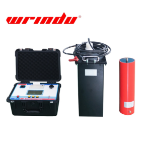
Click the picture to know more about Wrindu VLF HV Tester.
Why Is Cable Testing Important for Aging Power Grids?
As power cables age, their insulation naturally degrades. If left unmonitored, minor imperfections can turn into catastrophic failures. Proactive cable testing and diagnostics allow utility companies to find these weak spots early. This helps teams plan maintenance during scheduled downtime rather than dealing with costly emergency repairs.
What Kind of Cable Was Tested in This Case Study?
The diagnostic team evaluated a 12/20 kV XLPE underground cable that was installed back in 2007.
-
Total Length: 995 meters
-
The Challenge: The exact number and precise locations of the cable joints (splices) were completely unknown before the test.
-
The Equipment: Technicians used a van-mounted Megger TDM4540 system equipped with an internal partial discharge (PD) coupler.
What Did the Tan Delta (Dielectric Loss) Measurement Reveal?
The first step in the assessment was a Tan Delta measurement, which checks the overall health of the cable’s insulation.
The results showed elevated dielectric losses across all three phases, classifying the cable’s condition as “critical” according to the IEEE 400.2-2014 standard. Interestingly, Phase L2 showed significantly higher losses than the other two phases. This global measurement signaled that something was wrong, likely at a specific joint or termination, but Tan Delta alone cannot pinpoint the exact location of a defect.
How Did Partial Discharge (PD) Testing Locate the Defect?
To find the exact location of the problem, the team performed a Partial Discharge (PD) measurement using three different voltage waveforms: DAC (Damped AC), VLF CR/Slope, and 0.1 Hz VLF Sine.
The results revealed a major difference in how sensitive these testing methods are:
-
The Discovery: Both the DAC and VLF CR/Slope methods successfully detected a defect in Phase L2 at around the 280-meter mark, pointing directly to a faulty cable joint.
-
The Blind Spot: Surprisingly, the 0.1 Hz VLF Sine wave method failed to detect this weak spot entirely—even when the test voltage was raised to 1.7 times the nominal voltage ($1.7 U_o$).
The Outcome: Thanks to the accuracy of the DAC and VLF CR/Slope technologies, the utility company safely replaced the faulty joint at 280 meters. Upon opening the old joint, they found poor workmanship, including a lack of assembly paste and sealing tape. A follow-up test confirmed the cable was back in optimal condition.
Conclusion: Which Diagnostic Waveform Should You Choose?
This case study proves that relying on just one type of testing waveform can leave dangerous defects hidden in your network. While the 0.1 Hz VLF Sine wave is popular, it completely missed a critical fault in this scenario. Combining Tan Delta for global health checks with DAC or VLF CR/Slope for precise partial discharge location is the most reliable way to secure your cable infrastructure.
Frequently Asked Questions (FAQs)
What is the difference between Tan Delta and Partial Discharge testing?
Tan Delta testing provides a “global” health check of the entire cable’s insulation, telling you if the cable is degrading generally. Partial Discharge (PD) testing acts like an X-ray that can pinpoint the exact “local” spot where an electrical defect is actively occurring.
Why did the 0.1 Hz VLF Sine wave fail to detect the cable defect?
Different voltage waveforms place different types of electrical stress on cable insulation. In this case study, the 0.1 Hz VLF Sine wave did not create the necessary conditions to trigger partial discharge at the faulty joint, proving it has lower detection sensitivity for certain types of craftmanship defects compared to DAC and VLF CR/Slope.
How does poor workmanship affect medium-voltage cable joints?
Poor installation—such as forgetting to use enough assembly paste or failing to wrap sealing tape correctly—leaves tiny air gaps and voids inside the joint. Over time, high voltage causes electrical sparks (partial discharges) inside these voids, which slowly destroys the insulation until the joint short-circuits.
