

Understanding Transformer Winding Resistance: A Complete Guide
Learn what transformer winding resistance is, why it changes, how to test it with a DC winding resistance tester, and how resistance analysis helps detect transformer faults.
Maintaining a reliable power grid requires keeping a close eye on your equipment. One of the most critical health indicators for a power transformer is its winding resistance.
This guide breaks down what winding resistance is, why it changes, and how to test it to keep your electrical systems running smoothly.
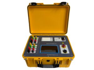
Click the image to know more about Transformer DC Resistance Tester.
What Is Transformer Winding Resistance?
Transformer winding resistance is the internal opposition to electricity flowing through the transformer’s copper or aluminum coils. Think of it as a measurement of how much energy the wires fight against the current. This resistance is a natural property of the conductor metals, and keeping it within a specific range ensures the transformer works efficiently without overheating.
Why Does Winding Resistance Matter for Power Systems?
Measuring winding resistance helps you catch hidden mechanical and electrical problems before they cause costly blackouts.
If a transformer’s resistance readings are too high, it usually means the system is wasting energy as heat ($I^2R$ losses). In fact, winding resistance causes roughly 20% to 30% of all load-related energy losses in distribution transformers. Routinely checking these values allows engineers to track equipment health over time and fix issues during scheduled maintenance.
What Causes Changes in Winding Resistance?
Several physical factors alter how much resistance a transformer coil has:
-
Wire Dimensions: Longer or thinner wires naturally create more resistance.
-
Metal Type: Copper features a lower natural resistance than aluminum, making it more efficient for heavy-duty applications.
-
Heat: Resistance rises as the transformer gets hotter. For copper windings, resistance increases by about 0.4% for every 1°C jump in temperature.
-
Wear and Defects: Loose physical connections, internal short circuits, and metal oxidation over time will all spike resistance levels.
How Do You Test Transformer Winding Resistance?
Technicians measure winding resistance by injecting a stable, low-voltage DC current (typically 5A to 20A for larger power transformers) through the coils.
To get accurate readings:
-
Completely de-energize the transformer.
-
Connect a digital winding resistance tester using four-wire Kelvin leads to eliminate testing errors from the leads themselves.
-
Wait up to a minute for the current to stabilize past the coil’s natural inductance.
-
Convert your findings to a standard reference temperature of 75°C to accurately compare them against the original factory settings.
If your current readings drift more than 2% away from the factory baseline data, it is a strong sign of an internal fault.
What Are the Most Common Transformer Resistance Problems?
When resistance readings deviate from normal baselines, they usually point to one of these common system failures:
-
Short Circuits: Broken insulation can cause individual coil turns to touch, shortening the electrical path.
-
Tap Changer Defects: Faulty contacts inside the tap changer create localized resistance spikes.
-
Loose Joints: Loose or corroded bolts on bushings and internal connections interrupt smooth current flow.
If you notice an imbalance between different phases in a three-phase system, inspect the connections, retighten the hardware, and run individual phase tests to isolate the defect.
Frequently Asked Questions
Why do we measure transformer winding resistance with DC instead of AC current?
We use DC current because it bypasses the inductive reactance of the transformer coils. An AC current would experience both resistance and inductance (impedance), making it impossible to isolate the pure ohmic resistance of the metal wires.
How do you normalize transformer resistance readings for temperature changes?
Because temperature directly changes metal resistivity, you must convert all field measurements to a standard 75°C reference point using a temperature correction formula:
(Where $R_1$ is the measured resistance at temperature $T_1$, and $R_2$ is the calculated resistance at the target temperature $T_2$.)
What percentage of resistance deviation indicates a transformer fault?
A variance of 1% to 2% from the factory nameplate standard generally points to minor connection wear. However, any deviation exceeding 3% to 5% indicates serious issues like shorted turns or severe tap changer degradation that require immediate troubleshooting.
