

Why a 2% Transformer Resistance Shift Means Trouble
Learn what a 2% transformer winding resistance deviation means, how to calculate resistance imbalance, identify internal faults, and prevent transformer failures.
When a power transformer shows a 2% variance in winding resistance, it is not just a minor stat—it is an early warning sign of severe internal damage. In high-voltage power systems, perfect balance is everything. Even a slight asymmetry can quickly trigger localized hotspots, destroy insulation, and cause catastrophic equipment failure.
To keep your power grid safe and avoid unexpected blackouts, you need to understand what this 2% threshold really means, how to calculate it, and what steps to take next.
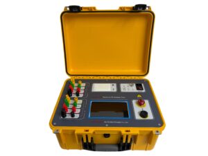
Click the image to know more about Transformer DC Resistance Tester.
Why Is the 2% Transformer Resistance Rule So Crucial?
A 2% difference in winding resistance serves as a critical dividing line between normal operational wear and a developing asset fault. Three-phase transformers rely on perfect magnetic and electrical balance across all phases. When a deviation crosses the 2% mark, it proves that the system is actively degrading.
From an engineering and manufacturing standpoint, three major issues usually cause this specific imbalance:
-
Short Circuits Between Turns: If even a single loop within a winding shorts out, the electrical path shortens. This drops the resistance in that phase and spikes local eddy currents.
-
Loose Internal Connections: Heavy operational vibrations over time can loosen internal bolts and busbars, adding unwanted contact resistance.
-
Tap Changer Wear: Carbon buildup, pitting, or physical deformation on the moving contacts of a tap changer introduces dangerous, localized resistance.
How Do You Use Nameplate Data to Check Resistance Tolerances?
You cannot accurately evaluate field measurements without comparing them to the transformer’s original baseline—its factory nameplate data. This nameplate records the precise resistance measured before shipment, corrected to a standard reference temperature (typically 75°C or 85°C).
Because copper and aluminum change resistance as temperatures shift, you must first convert your field readings using the standard material formula:
(Note: $T_{material}$ is 234.5 for copper and 225 for aluminum)
After correcting the temperatures, use the phase-to-phase formula to find the exact percentage variance:
Here is how to interpret your results and take action:
-
Under 1% (Optimal): The transformer is healthy. Continue standard monitoring.
-
1% to 2% (Warning): Test more frequently and run a Dissolved Gas Analysis (DGA) to check for early issues.
-
Over 2% (Critical): Isolate the unit immediately to inspect the internal connections and tap changer.
What Internal Faults Cause Unequal Winding Resistance?
Unequal resistance values are direct physical symptoms of mechanical deformation or broken components inside the transformer tank. While these assets look solid on the outside, they handle massive electrodynamic and radial forces during short-circuit events.
Common physical causes include:
-
Snapped or fractured conductor strands.
-
Coil warping, telescoping, or shifting due to external electrical faults.
-
Oxidized, pitted, or worn contacts inside the On-Load Tap Changer (OLTC).
Advanced testing instruments can sweep through every individual tap position. This helps technicians figure out if the problem is isolated to a specific tap contact or if the issue sits deep within the main winding body itself.
Which Tools Best Map and Detect Resistance Deviations?
Standard multimeters cannot saturate the massive inductive load of a large power transformer core. To get stable, micro-ohm level accuracy, engineers must use specialized DC winding resistance meters.
The most effective diagnostic tools utilize:
-
High-Current DC Injection: Quickly overcomes winding inductance to stabilize readings.
-
Multi-Channel Simultaneous Testing: Measures high-voltage and low-voltage windings at the same time. This removes false positives caused by shifting ambient temperatures during the test.
-
Automated Deviation Matrices: Instantly calculates phase-to-phase variances on-screen for immediate field analysis.
How Does Temperature Distort Winding Measurements?
Metals have a positive temperature coefficient, meaning their resistance goes up as they get hotter. If a transformer has uneven internal temperatures—such as hot oil at the top and cooler oil at the bottom—raw field measurements taken at different times of the day will be highly inaccurate.
To avoid false alarms or missed faults, the transformer should stay offline for several hours to reach thermal equilibrium before testing. Always use precision sensors to log the exact oil temperature so your mathematical correction matches the factory baseline.
Why Do Factories Enforce Stricter Resistance Limits Than Field Standards?
While international field standards (like IEEE and IEC) flag 2% as the limit for field intervention, manufacturers maintain much tighter thresholds. New units leaving a quality control floor generally must show phase-to-phase deviations below 0.5% to 1%.
Enforcing strict limits at the factory ensures that the asset has zero manufacturing flaws—like uneven wire tension or sub-optimal crimping—giving the buyer a flawless system with its full operational lifespan intact.
Does a 2% Resistance Shift Affect Dissolved Gas Analysis (DGA)?
Yes. A 2% resistance imbalance generates a localized hotspot. As load current passes through this high-resistance fault zone, temperatures can quickly spike between 300°C and 700°C, causing the surrounding transformer insulation oil to crack and decompose into combustible fault gases.
By tracking Dissolved Gas Analysis (DGA) trends, you can look for these specific indicators:
-
Methane ($CH_4$) & Ethane ($C_2H_6$): Indicate low-to-medium temperature thermal faults.
-
Ethylene ($C_2H_4$): Signals high-temperature hotspots (over 300°C), common with failing tap changers.
-
Acetylene ($C_2H_2$): Warns of active electrical arcing, which requires immediate shutdown.
How Should Engineers Respond to a 2% Resistance Deviation?
If your field diagnostics confirm a temperature-corrected deviation of 2% or more, treat it as an emergency and take action immediately:
-
Isolate the Unit: Safely de-energize and take the transformer offline.
-
Clean and Verify: Clean the bushing terminals and verify that your test leads are tightly clamped to eliminate surface contact errors.
-
Run a Tap Sweep: Re-test across all tap changer positions. If the deviation disappears on certain steps, the fault is inside the tap changer mechanism. If it stays constant, the problem is in the main phase windings.
-
Cross-Reference Data: Review recent DGA gas reports and perform a transformer turns-ratio (TTR) test to rule out an active inter-turn insulation failure before deciding on an internal inspection or factory rebuild.
Frequently Asked Questions (FAQs)
What is the maximum allowable limit for transformer winding resistance deviation?
For transformers out in the field, standard international guidelines (IEEE/IEC) state that the winding resistance deviation must remain under 2% between phases or when compared to the original factory nameplate data. New transformers at the factory must meet stricter limits, usually under 0.5%.
Why does a shorted turn cause a transformer’s winding resistance to drop?
An inter-turn short circuit creates an electrical shortcut that bypasses a portion of the coil. Because the current travels along a physically shorter path length, the overall measured DC resistance for that specific phase decreases.
Can a loose connection cause a high transformer resistance reading?
Yes. Corroded bolts, bad crimps, or degraded tap changer contacts introduce high localized contact resistance. This extra resistance increases the total measured DC value for that phase, pushing it past the acceptable 2% threshold.
How often should you test transformer winding resistance?
Winding resistance should be tested during factory acceptance, at initial installation commissioning, during routine maintenance cycles (every 1 to 3 years), and immediately after the transformer experiences a major through-fault or a protective relay trip.
