

How Do Temperature and Thermal EMF Affect Micro-Ohmmeter Accuracy?
Discover how to calculate total micro-ohmmeter measurement error using accuracy, range, temperature, and calibration factors. Improve low resistance testing accuracy for transformers and electrical equipment.
Accurate low-resistance testing is not only determined by the instrument itself. Environmental conditions during measurement can significantly affect the final result.
When testing transformers, circuit breakers, and busbars, engineers must consider temperature changes and thermal electromotive force (EMF), especially when measuring micro-ohm-level resistance.
Even a very small unwanted voltage can create a large error when the measured resistance is extremely low.
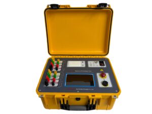
Click the image to know more about Transformer DC Resistance Tester.
Why Does Temperature Change Micro-Ohmmeter Measurement Results?
Electrical conductors such as copper and aluminum have a positive temperature coefficient. This means their resistance increases as the temperature rises.
For example:
- Copper resistance increases as winding temperature increases.
- Aluminum conductors also show resistance changes under different temperatures.
- Outdoor testing conditions can vary significantly during the day.
If resistance measurements are taken at different temperatures, the results cannot be directly compared.
This is especially important for:
- Transformer winding resistance testing
- Generator stator testing
- Busbar connection inspection
- Circuit breaker contact resistance measurement
To achieve reliable comparison, test results should be corrected to a standard reference temperature.
Temperature compensation allows engineers to compare current measurements with:
- Factory acceptance test data
- Previous maintenance records
- Manufacturer reference values
What Is Thermal EMF and Why Does It Affect Micro-Ohm Testing?
Thermal EMF is one of the biggest challenges in ultra-low resistance measurement.
When two different metals are connected together and there is a temperature difference between the connection points, a small voltage is generated due to the Seebeck effect.
The generated voltage can be expressed as:
Vthermal = α × ΔT
Where:
- α = Seebeck coefficient of the material connection
- ΔT = temperature difference
Although this voltage is very small, it can seriously affect micro-ohm measurements because the actual test voltage is also extremely low.
For example, when measuring a contact resistance of only a few micro-ohms, a small thermal voltage may create a significant percentage error.
How Do Four-Wire Kelvin Testing and Current Reversal Reduce Errors?
Professional micro-ohmmeters use advanced measurement methods to eliminate unwanted resistance and thermal voltage effects.
The most important technologies include:
Four-Wire Kelvin Connection
A four-wire Kelvin connection separates:
- Current injection cables
- Voltage measurement cables
The current cables provide stable testing current, while the sensing cables measure only the voltage drop across the test object.
This removes errors caused by:
- Cable resistance
- Clamp resistance
- Contact resistance
As a result, engineers can obtain more accurate low-resistance measurements.
Automatic Current Reversal Technology
Advanced micro-ohmmeters can reverse the test current direction to remove thermal EMF influence.
The instrument performs two measurements:
- Positive current measurement
- Negative current measurement
The resistance calculation becomes:
R = (V1 – V2) / (2 × I)
Because the thermal voltage remains constant while the current direction changes, the system can mathematically eliminate the unwanted voltage.
This improves measurement stability in:
- Substations
- Power plants
- Outdoor environments
- High-current equipment testing
How Can Engineers Calculate the Total Measurement Error?
A reliable measurement requires combining all possible error sources.
The total uncertainty normally includes:
- Reading accuracy error
- Range error
- Temperature influence
- Environmental effects
The calculation method is:
Total Error = Reading Error + Range Error + Temperature Error
For example, consider testing a generator stator winding with:
- Target resistance: 1.500 mΩ
- Accuracy: ±(0.2% of reading + 0.02% of range)
- Selected range: 2 mΩ
- Ambient temperature: 38°C
Step 1: Calculate Reading Error
Reading error:
1.500 mΩ × 0.002
= ±0.003 mΩ
= ±3 μΩ
Step 2: Calculate Range Error
Range error:
2.000 mΩ × 0.0002
= ±0.0004 mΩ
= ±0.4 μΩ
Step 3: Calculate Temperature Error
The standard calibration temperature is normally around 23°C.
The testing temperature is 38°C, creating a temperature difference.
After applying the temperature coefficient:
Temperature error:
= ±0.75 μΩ
Step 4: Calculate Total Measurement Uncertainty
Total error:
±(3 μΩ + 0.4 μΩ + 0.75 μΩ)
= ±4.15 μΩ
The final measurement can therefore be reported as:
1.500 mΩ ±0.277%
This complete calculation provides stronger evidence for:
- Utility acceptance testing
- Factory quality inspection
- Certification audits
Does a Higher Test Current Always Improve Micro-Ohmmeter Accuracy?
A higher test current does not automatically make the instrument more accurate.
However, it can improve measurement stability by increasing the voltage signal across the resistance being tested.
According to Ohm’s Law:
V = I × R
A higher current creates a larger voltage drop, which improves the signal-to-noise ratio (SNR).
This helps reduce the influence of:
- Electrical interference
- Background noise
- Measurement instability
However, excessive current can also create heating problems.
The heat generated is:
P = I²R
Too much current may increase the temperature of the tested connection and cause the resistance value to rise artificially.
Therefore, engineers should balance:
- Measurement stability
- Test duration
- Thermal effects
- Equipment safety
What Test Current Should Be Used for Different Applications?
The correct test current depends on the application.
Typical recommendations include:
| Application | Recommended Test Current |
|---|---|
| Small transformer windings | 1A–10A |
| Medium transformer windings | 10A–50A |
| Circuit breaker contacts | 50A–200A |
| Large busbars | 100A–200A |
High-current testing is useful for low-resistance applications, but the current should always match the equipment design.
Using maximum current for every test is not always the best solution.
Why Is Excessive Test Current a Common Testing Mistake?
Some technicians believe that increasing current will automatically improve accuracy.
However, excessive current may cause:
- Local heating
- Resistance increase
- Unstable readings
- Possible component stress
For example, small contacts or delicate transformer windings may experience temperature changes during long high-current testing.
A better approach is:
- Use stable current output
- Apply suitable test duration
- Use software filtering
- Monitor temperature changes
Reliable measurement depends on a complete testing method, not only higher current.
When Should Manufacturers Choose Custom OEM Micro-Ohmmeters?
Standard micro-ohmmeters are suitable for general field inspection. However, some factories require customized solutions for production lines.
OEM micro-ohmmeter solutions are useful when manufacturers need:
- Automatic testing sequences
- Multiple measurement channels
- PLC communication
- RS485 or industrial interfaces
- Customized test limits
- Production data integration
Industries that often require customized systems include:
- Transformer manufacturing
- EV battery production
- High-power relay manufacturing
- Railway traction equipment
- Renewable energy equipment
Customized systems help factories improve:
- Testing speed
- Production consistency
- Data traceability
- Quality control
How Does Micro-Ohmmeter Accuracy Affect Renewable Energy Systems?
Accurate low-resistance testing is becoming increasingly important in renewable energy infrastructure.
Applications include:
- Solar power plants
- Wind farms
- Battery energy storage systems (BESS)
- High-voltage transmission networks
Large renewable energy systems contain thousands of electrical connections.
A small increase in connection resistance can create:
- Heat generation
- Energy loss
- Insulation damage
- Equipment failure
For example:
A 10 μΩ hidden resistance increase under a 2000A load creates:
P = I²R
= (2000A)² × 10 μΩ
= 40W heat loss
A continuous hotspot at a connection point can gradually damage surrounding materials.
Therefore, accurate and traceable micro-ohm testing plays an important role in improving renewable energy reliability.
