

How Does a Ground Resistance Tester Work and What Are Its Main Functions?
Learn how a ground resistance tester works, its main functions, testing methods, and applications. Discover how earth resistance testers improve grounding safety for substations, transformers, and industrial systems.
Ground resistance testing is an important process used to evaluate the performance of electrical grounding systems.
A reliable grounding system protects electrical equipment and personnel by providing a safe path for fault current, lightning current, and leakage current to flow into the earth.
However, the accuracy of grounding evaluation depends heavily on the quality and capability of the testing instrument.
A ground resistance tester, also called an earth resistance tester, is a professional measuring device designed to determine the resistance between a grounding electrode and the earth.
By applying a controlled test current and measuring voltage response, the instrument calculates the grounding resistance value and helps engineers verify whether grounding systems meet safety requirements.
Ground resistance testers are widely used in:
- Power substations
- Transformer grounding systems
- Industrial facilities
- Renewable energy plants
- Telecommunication towers
- Electrical installation projects
Click the picture to know more about Wrindu Earth Resistance Tester.
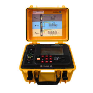
Click the picture to know more about Wrindu Earth Resistance Tester.
What Is a Ground Resistance Tester?
A ground resistance tester is an electrical testing instrument used to measure the resistance of a grounding system.
The main purpose of the tester is to determine how effectively a grounding electrode can discharge unwanted electrical currents into the earth.
A grounding resistance measurement usually includes:
- A grounding electrode under test
- Auxiliary test electrodes
- Test cables
- A measuring instrument
The tester generates a small AC test current and measures the voltage difference produced in the soil.
Using Ohm’s Law:
R = V / I
The instrument calculates the grounding resistance automatically.
Where:
- R = Ground resistance
- V = Voltage drop
- I = Test current
The final measurement indicates whether the grounding system provides a sufficiently low-resistance path.
How Does a Ground Resistance Tester Work?
A ground resistance tester operates by creating a temporary electrical circuit between the grounding system and auxiliary electrodes.
The basic testing process includes three steps.
How Does the Tester Apply Test Current?
During measurement, the instrument sends a controlled AC current into the earth through the current electrode.
AC test current is commonly used because it reduces polarization effects that may occur when using direct current.
The current flows through the soil between:
- The grounding electrode
- The auxiliary current electrode
This creates a measurable electrical condition for resistance calculation.
How Does the Tester Measure Voltage Drop?
After applying test current, the instrument measures the voltage difference between:
- The grounding electrode
- The potential electrode
The measured voltage represents the potential change caused by current flowing through the earth.
A stable voltage measurement is essential because even small errors may affect the final resistance result.
How Does the Tester Calculate Ground Resistance?
The tester combines:
- Applied test current
- Measured voltage drop
and calculates the resistance value automatically.
Modern digital ground resistance testers display the result directly, reducing manual calculation errors and improving field efficiency.
What Are the Main Functions of a Ground Resistance Tester?
A professional ground resistance tester provides several functions to support electrical safety inspections.
How Does a Ground Resistance Tester Measure Ground Resistance?
The primary function is measuring the resistance between a grounding system and the earth.
Depending on the model, the tester may support:
- 2-point resistance measurement
- 3-point fall-of-potential testing
- 4-point soil resistivity testing
- Selective grounding resistance testing
- Clamp-on grounding measurement
These functions allow engineers to select the most suitable method according to site conditions.
How Does a Ground Resistance Tester Perform 3-Point Testing?
The 3-point test is one of the most common functions in professional ground resistance testers.
The instrument connects three terminals:
- E terminal → Ground electrode
- P terminal → Potential electrode
- C terminal → Current electrode
During testing:
- The tester injects current through the earth.
- The voltage between electrodes is measured.
- Ground resistance is calculated automatically.
This method provides accurate results for:
- Transformer grounding
- Substation grounding grids
- Industrial grounding networks
How Does a Ground Resistance Tester Support Soil Resistivity Testing?
Some advanced testers can perform 4-point soil resistivity measurement.
Soil resistivity testing helps engineers understand how easily current flows through the ground.
The results are useful for designing:
- Substation grounding systems
- Lightning protection systems
- Large grounding grids
Factors affecting soil resistivity include:
- Soil moisture
- Temperature
- Soil composition
- Geological conditions
What Are the Key Features of a Professional Ground Resistance Tester?
Different testers have different capabilities, but professional instruments usually include several important features.
Why Is Measurement Accuracy Important in Ground Resistance Testing?
Accuracy directly affects grounding system evaluation.
A high-quality tester should provide:
- Stable measurements
- Repeatable results
- Low measurement uncertainty
Accurate testing helps engineers identify:
- Poor grounding connections
- Aging electrodes
- Increased soil resistance
- Potential safety risks
Why Is Interference Resistance Important for Ground Testing?
Electrical environments often contain interference sources such as:
- Power transformers
- Transmission lines
- Industrial equipment
These electrical noises may affect measurement results.
Advanced ground resistance testers use interference rejection technology to improve reliability in complex environments.
Why Is Portable Design Important for Ground Resistance Testers?
Ground resistance testing is often performed outdoors.
Engineers may need to work in:
- Remote substations
- Construction sites
- Solar farms
- Transmission facilities
Portable testers provide:
- Easy transportation
- Simple field operation
- Faster maintenance testing
How Do Engineers Use a Ground Resistance Tester in the Field?
A typical field testing procedure includes several steps.
Step 1: Check the Grounding System
Before testing:
- Identify the grounding electrode
- Inspect connection points
- Confirm tester condition
This ensures reliable measurement results.
Step 2: Install Auxiliary Electrodes
For a 3-point test:
Install:
- Current electrode
- Potential electrode
according to recommended spacing requirements.
Correct electrode placement is important because incorrect distances may cause measurement errors.
Step 3: Connect the Tester
Connect:
- Ground electrode to E terminal
- Potential electrode to P terminal
- Current electrode to C terminal
Ensure all cables have good contact.
Step 4: Start Measurement
The tester applies current and measures voltage automatically.
The resistance value appears on the display after calculation.
Step 5: Analyze the Result
Engineers should compare the measured value with:
- Project requirements
- Electrical standards
- Historical test records
Abnormal increases may indicate grounding system problems.
Where Are Ground Resistance Testers Commonly Used?
Ground resistance testers are widely applied in different electrical fields.
How Are Ground Resistance Testers Used in Power Substations?
Power utilities use grounding testers to inspect:
- Transformer grounding
- Switchgear grounding
- Substation earth grids
Reliable grounding helps protect high-voltage equipment from fault conditions.
How Are Ground Resistance Testers Used in Industrial Plants?
Industrial facilities use grounding tests to protect:
- Motors
- Control systems
- Production equipment
- Electrical distribution systems
Regular testing helps reduce unexpected equipment failures.
How Are Ground Resistance Testers Used in Renewable Energy Systems?
Solar and wind power facilities require effective grounding systems.
Testing applications include:
- Lightning protection inspection
- Inverter grounding verification
- Equipment safety evaluation
How Can Wrindu Ground Resistance Testers Help Engineers?
Wrindu provides professional electrical testing solutions for power utilities, industrial users, and electrical engineers.
Wrindu ground resistance testing equipment is designed to provide:
- Accurate resistance measurement
- Reliable field operation
- Easy testing procedures
- Stable measurement results
With advanced manufacturing technology and strict quality management, Wrindu supports customers worldwide in improving grounding safety and electrical system reliability.
FAQs
What is a ground resistance tester used for?
A ground resistance tester is used to measure the resistance between a grounding electrode and the earth to verify grounding system performance.
How does an earth resistance tester work?
An earth resistance tester applies a controlled test current into the soil and measures voltage drop to calculate grounding resistance.
What is the difference between a multimeter and a ground resistance tester?
A multimeter measures basic electrical parameters such as voltage and resistance, while a ground resistance tester is specifically designed to measure earth grounding resistance.
Can a ground resistance tester measure transformer grounding resistance?
Yes. Ground resistance testers are commonly used for transformer grounding and substation earth grid inspections.
Why is AC current used in ground resistance testing?
AC test current reduces polarization effects and provides more stable grounding resistance measurements.
How accurate is a digital ground resistance tester?
Accuracy depends on instrument quality, testing method, electrode placement, and environmental conditions.
What accessories are needed for ground resistance testing?
Typical accessories include:
- Test cables
- Auxiliary electrodes
- Carrying case
- Connection clamps
How often should a ground resistance tester be used?
Testing frequency depends on system importance, regulations, and maintenance requirements. Many facilities perform grounding tests during regular preventive maintenance.
Conclusion
A ground resistance tester is an essential instrument for evaluating electrical grounding system performance.
By applying controlled current, measuring voltage drop, and calculating resistance automatically, the tester helps engineers confirm whether grounding systems provide effective protection.
Professional ground resistance testers with accurate measurement functions, interference resistance, and portable design improve testing efficiency in substations, industrial facilities, and renewable energy projects.
Regular grounding resistance measurement helps detect problems early, improve electrical safety, and maintain reliable power system operation.
