

Primary Current Injection Testing: Complete Guide to Principles, Procedures, Applications, and Test Equipment
Learn how primary current injection testing works, how to test circuit breakers and CTs, calculate test current, and choose the right injection tester.
Primary current injection testing is an electrical testing method that sends a controlled current through the primary circuit of electrical equipment. Engineers use this method to check current-carrying paths, evaluate current transformer (CT) response, and verify the operation of associated protection systems under suitable test conditions.
A primary current injection tester supplies the test current required for the application. The test current, duration, connection method, and acceptance criteria depend on the equipment under test and the purpose of the test.
This guide explains how primary current injection testing works, when engineers use it, how it differs from secondary injection testing, and how to select suitable test equipment.
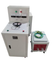
Click the image to know more about 6000A Primary Current Injection Tester.
What Is Primary Current Injection Testing?
Primary current injection testing is a method of applying a controlled electrical current directly to a primary current path. The current passes through the conductors and equipment included in the test circuit.
Engineers use the results to evaluate electrical connections, current transformers, circuit breaker operation, and associated protection functions, depending on the test setup.
For example, a circuit breaker primary injection test sends current through the breaker’s main current path. If the breaker has an overcurrent trip function, the test can help verify whether the protection system responds according to its configured settings and specified operating characteristics.
Primary current injection testing differs from a visual inspection or a simple continuity check because it can evaluate equipment under a defined current load. However, the test does not automatically verify every electrical, mechanical, or protection function.
How Does a Primary Current Injection Tester Work?
A primary current injection tester converts its input power into a controlled, high-current output suitable for the test application. Depending on its design, the equipment may use a transformer-based current source, electronic control, or another current-generation arrangement.
The operator connects the tester to the circuit under test using appropriately rated cables and connections. The tester then supplies the selected current for the required duration while the operator records the relevant response.
A typical test involves the following stages:
- Set the test objective. Identify whether the test will evaluate a circuit breaker’s trip response, a CT circuit, an electrical connection, or another function.
- Prepare the equipment. Check the equipment rating, test requirements, connection diagram, and applicable safety procedures.
- Connect the current source. Connect the tester to the specified primary current path using suitable cables and terminals.
- Apply the test current. Increase the current to the required value according to the approved test procedure.
- Measure the response. Record the injected current, elapsed time, trip response, or other required measurements.
- Compare the results. Evaluate the recorded results against manufacturer specifications, relay settings, applicable requirements, or approved acceptance criteria.
The exact procedure depends on the equipment and test objective. Some testers provide automatic current regulation, timed testing, or automatic trip-time measurement, while other functions require external instruments or additional accessories.
Why Is Primary Current Injection Testing Important?
Primary current injection testing helps engineers verify the behavior of electrical equipment under a defined current condition. It is particularly useful when the test needs to include the primary current path rather than only an electronic relay input.
Circuit breaker verification: The test can help confirm that a breaker and its associated overcurrent protection respond at the expected current and within the specified time, where the test arrangement includes the relevant protection chain.
Current transformer verification: Comparing injected primary current with the measured CT secondary output can help assess the transformation ratio and current response. Separate procedures may be needed to verify polarity, wiring, accuracy, and other CT characteristics.
Connection assessment: Current injection can help identify excessive resistance or abnormal heating in a connection when combined with suitable voltage-drop, resistance, temperature, or other measurements. Current injection alone does not establish that every connection meets its resistance limit.
Commissioning and maintenance: Engineers can use the test to check selected functions after installation, maintenance, or equipment replacement. The scope must be defined before testing because primary injection does not replace all required commissioning tests.
Which Electrical Equipment Can Be Tested With Primary Current Injection?
Primary current injection is used in several types of electrical testing. The suitable current, connection arrangement, and measurements vary by equipment.
| Equipment under test | Main test objective | Typical observations or measurements |
|---|---|---|
| Low-voltage circuit breaker | Verify overcurrent trip response | Injected current, trip time, trip indication |
| Molded-case circuit breaker (MCCB) | Check selected thermal or magnetic trip functions | Current and trip time, according to the test objective |
| Air circuit breaker (ACB) | Verify selected protection and operating functions | Trip response and relevant current measurements |
| Current transformer (CT) | Check current transformation and connected circuit response | Primary current, secondary current, ratio comparison |
| Switchgear current path | Assess selected current-carrying connections | Current, voltage drop, resistance, or temperature as required |
| Overcurrent protection chain | Check the response of the included primary and secondary components | Injected current, relay response, trip command, breaker operation |
Not every primary current injection tester supports every application in this table. The required output current, output voltage, duty cycle, connection arrangement, and accessories must match the equipment being tested.
What Is the Difference Between Primary and Secondary Injection Testing?
Primary and secondary injection testing differ mainly in where the test signal enters the protection system.
Primary injection sends current through the relevant primary current path. Secondary injection applies a test signal directly to the secondary circuit, commonly at the protective relay or another specified test point.
| Comparison | Primary injection testing | Secondary injection testing |
|---|---|---|
| Test input | Primary current path | Secondary protection circuit |
| Main purpose | Check the included primary path and associated response | Check relay measurement, settings, logic, and selected outputs |
| CT response | Can include CT transformation and secondary circuit response | Normally bypasses the CT by injecting at the secondary test point |
| Breaker trip verification | Possible when the test arrangement includes the required trip chain | Possible when the test arrangement includes the required trip circuit and breaker |
| Current requirement | May require hundreds or thousands of amperes, depending on the application | Uses the relay’s specified secondary input range |
| Test setup | Often requires high-current cables and suitable connections | Often uses a relay test set and secondary wiring |
| Typical limitation | High-current connections, power requirements, and thermal constraints | Does not independently prove the primary conductor path or CT response when these are bypassed |
Primary injection generally provides a broader check of the current path included in the test. Secondary injection is often more convenient for detailed relay testing because the test signal can be applied directly to the protection device.
The two methods serve different purposes. Engineers may need both to verify a complete protection system.
How Do You Perform a Circuit Breaker Primary Injection Test?
A circuit breaker primary injection test checks the response of the breaker and the protection functions included in the test arrangement. The procedure must follow the breaker manufacturer’s instructions and the approved site testing plan.
Step 1: Identify the breaker and protection settings
Record the breaker model, rated current, trip unit type, relevant pickup settings, and applicable time-current characteristics. Confirm which protection functions need to be tested.
Step 2: Isolate and prepare the equipment
Place the equipment in the required safe condition. Apply the site’s isolation, lockout/tagout, verification, and grounding procedures as applicable. Follow the manufacturer’s instructions for connecting the test equipment.
Step 3: Connect the current injection tester
Connect the tester to the specified terminals so the current flows through the intended primary path. Check cable ratings, terminal security, polarity where relevant, and the integrity of all connections.
Step 4: Select the test current
Choose the test current according to the protection setting and the function under test. A pickup test, a time-delay test, and an instantaneous trip test may require different current levels and procedures.
Step 5: Apply current and record the response
Apply the required current for the specified period. Record the actual injected current and the measured trip time or other relevant response. Avoid exceeding the equipment’s permitted current and thermal limits.
Step 6: Compare the results with the acceptance criteria
Compare the recorded results with the manufacturer’s published tolerances, configured settings, and applicable test requirements. Investigate any unexpected response before returning the equipment to service.
Step 7: Restore the equipment
Remove the test connections and restore the system according to the approved procedure. Confirm that the equipment is in the required operating condition and document the test results.
A single current value is not sufficient to verify every trip function. The test plan should specify the target current, test duration, expected response, and acceptance criteria for each function.
How Do You Calculate the Required Primary Injection Test Current?
The required test current depends on the equipment rating, protection settings, and test objective. Engineers should not select an arbitrary current simply because the tester can produce it.
For a circuit breaker with a defined current-based pickup setting, the test current can be expressed as:
Test current = Pickup setting × Selected test multiple
For example, assume a breaker has a documented long-time pickup setting of 400 A. If the approved test plan specifies a test at 1.5 times that setting, the target current is:
400 A × 1.5 = 600 A
This is an illustrative calculation, not a universal test requirement. The actual current and permitted duration must follow the breaker manufacturer’s instructions and the applicable test procedure.
For a CT ratio check, the nominal transformation ratio can be calculated as:
CT ratio = Rated primary current ÷ Rated secondary current
For example, a CT rated at 800/5 A has a nominal ratio of 160:1. At a primary current of 400 A, an ideal CT would produce 2.5 A on the secondary side, assuming the specified ratio applies under the test conditions.
Actual CT performance can be affected by the CT design, burden, wiring, and operating conditions. A simple current comparison does not replace a complete accuracy or protection-class test when one is required.
What Specifications Should You Check When Choosing a Primary Current Injection Tester?
The correct tester depends on the maximum required current, the equipment under test, and the duration of each test. Output current alone is not enough to determine whether a tester is suitable.
| Specification | Why it matters |
|---|---|
| Output current range | Determines whether the tester can reach the required test current |
| Output voltage or compliance voltage | Must be sufficient to drive the required current through the test circuit and connection resistance |
| Output power | Affects the tester’s ability to deliver current under the required load conditions |
| Duty cycle | Determines how long the tester can operate at a given current before cooling or a rest period is required |
| Current regulation | Helps maintain the selected current as the test circuit conditions change |
| Measurement accuracy | Affects confidence in the recorded current and timing results |
| Timer and trip detection | Determines whether the tester can measure the required trip time automatically |
| Cable and terminal ratings | Must match the current, temperature, connection, and safety requirements |
| Portability and supply requirements | Affect use in substations, workshops, and commissioning environments |
| Protection and safety features | May include overcurrent protection, thermal protection, and emergency stop functions, depending on the model |
Before choosing a tester, calculate the required current and estimate the load impedance of the complete test circuit. Confirm that the tester can deliver the required current for the specified duration without exceeding its output, thermal, or connection limits.
What Is the Difference Between a 1000 A and a 2000 A Primary Current Injection Tester?
The main difference is the maximum rated output current, but the higher-current model is not automatically the better choice for every application.
| Selection factor | 1000 A tester | 2000 A tester |
|---|---|---|
| Maximum rated current | Up to 1000 A, subject to model specifications | Up to 2000 A, subject to model specifications |
| Suitable test current | Applications requiring no more than its available output | Applications requiring current above the practical capability of the 1000 A model, up to the rated limit |
| Connection requirements | Must use connections rated for the actual test current | May require heavier cables and lower-resistance connections |
| Supply and output capability | Must meet the required current and load conditions | Must meet the required current, load, and duty-cycle conditions |
| Best selection basis | Required current, duration, and test setup | Required current, duration, and test setup |
These ratings are illustrative selection categories, not specifications for a particular Wrindu product. Actual output capacity may vary with output voltage, circuit resistance, supply conditions, and operating duration.
A tester should be selected from the test requirements rather than the maximum current rating alone.
Which Standards Are Relevant to Primary Current Injection Testing?
The applicable standards depend on the equipment being tested and the purpose of the test. A standard for circuit breaker design, CT performance, or protective relay requirements does not automatically prescribe one universal primary injection procedure for every application.
The following standards are useful starting points for identifying relevant requirements:
| Standard | General scope | Relevance to testing |
|---|---|---|
| IEC 60947-2 | Low-voltage circuit breakers | Relevant to breaker characteristics and performance requirements within its scope |
| IEC 61869-2 | Additional requirements for current transformers | Relevant to CT characteristics and performance |
| IEC 60255 series | Measuring relays and protection equipment | Relevant to applicable relay and protection equipment requirements |
| IEEE C37.09 | Test procedures for AC high-voltage circuit breakers rated on a symmetrical current basis | Relevant to the applicable high-voltage circuit breaker test scope |
The applicable edition, equipment rating, local requirements, and manufacturer’s instructions should be checked before a test procedure is approved. These references should not be interpreted as proof that a particular injection test is mandatory in every installation.
For a specific project, the test plan should identify the standard or specification that defines the required test method and acceptance criteria.
What Safety Precautions Are Required During Primary Current Injection Testing?
Primary current injection testing can involve dangerous current levels, hot conductors, strong magnetic fields, and unexpected equipment operation. A safe test requires a planned setup and controlled access to the test area.
Before starting a test:
- Confirm the isolation status of the equipment and follow the approved lockout/tagout procedure.
- Verify the required test connections and ensure that cables, clamps, and terminals are rated for the expected current.
- Secure all high-current connections to reduce the risk of arcing, overheating, or accidental disconnection.
- Keep personnel clear of exposed conductors and moving switching equipment.
- Check the tester’s supply requirements, grounding arrangements, protective devices, and emergency stop function.
- Apply the specified current and duration without exceeding equipment limits.
- Allow components to cool where required before handling or disconnecting them.
- Confirm the required equipment condition before removing isolation and returning the system to service.
Current transformers require particular care. An energized CT secondary must not be opened because a dangerous voltage can develop. CT secondary connections must be handled according to the approved procedure.
Only trained and authorized personnel should perform the test using the applicable safety rules and equipment instructions.
What Problems Can Occur During Primary Current Injection Testing?
Unexpected results may come from the equipment under test, the test connections, the tester’s output capability, or the selected test procedure.
| Observed problem | Possible causes | Recommended checks |
|---|---|---|
| Required current cannot be reached | Excessive circuit resistance, insufficient output capability, unsuitable supply conditions | Check the connection path, cable resistance, supply, and tester ratings |
| Breaker does not trip as expected | Incorrect settings, wrong test connection, incorrect current, or a protection function not included in the test | Verify the test plan, trip settings, connection diagram, and current measurement |
| Trip time differs from the expected value | Incorrect test multiple, timing method, equipment condition, or settings | Confirm the target current, test duration, applicable tolerance, and measurement method |
| CT secondary current is unexpected | Ratio or wiring issue, polarity error, burden effects, or measurement error | Check the CT nameplate, wiring, burden, instrument range, and test arrangement |
| Connections become excessively hot | Loose terminals, high contact resistance, unsuitable cables, or excessive test duration | Stop the test safely and inspect the connections after the equipment is in a safe condition |
| Test results vary between attempts | Inconsistent connections, current instability, changing thermal conditions, or measurement differences | Standardize the setup and confirm current regulation and measurement accuracy |
These are troubleshooting possibilities rather than definitive diagnoses. Engineers should investigate the actual test conditions and follow the manufacturer’s instructions before repeating a test.
How Can You Select the Right Primary Current Injection Tester for Your Application?
Start with the equipment you need to test, not the tester’s headline current rating. Identify the required current, target duration, test circuit resistance, and functions that must be verified.
Next, check whether the tester can deliver the required current under the actual load conditions. Review output voltage, duty cycle, current regulation, measurement capability, connection accessories, and available supply power.
Finally, confirm the intended test procedures and acceptance criteria. If you need to test circuit breakers, CTs, and switchgear connections, list the requirements for each application before comparing models.
Wrindu provides electrical testing equipment for power system testing applications. For a suitable primary current injection tester, the model selection should be based on the required current range, output capability, test duration, measurement functions, and intended equipment.
Contact Wrindu to discuss your application and confirm the technical specifications required for your test setup.
What Are the Most Common Questions About Primary Current Injection Testing?
What is the purpose of primary current injection testing?
Its purpose is to apply a controlled current through a primary current path to evaluate the response of the equipment and protection functions included in the test arrangement.
What is the difference between primary injection and secondary injection?
Primary injection passes current through the primary current path. Secondary injection applies a test signal directly to a secondary circuit, commonly at the protective relay or a designated test point.
Can a primary current injection tester test circuit breakers?
Yes, if the tester can supply the required current and the connection arrangement is suitable for the breaker and protection function being tested.
Can primary injection testing verify a current transformer?
It can help assess the CT transformation ratio and secondary current response under suitable conditions. Other CT characteristics may require separate tests.
How much current is required for a primary injection test?
The required current depends on the equipment rating, protection settings, test objective, and approved procedure. There is no single current value that applies to all primary injection tests.
Is primary current injection testing mandatory?
Requirements depend on the equipment, applicable standards, manufacturer instructions, project specifications, and local regulations. A test should not be described as universally mandatory without identifying the governing requirement.
Does primary injection testing replace secondary injection testing?
No. Primary injection and secondary injection verify different parts of a protection system. Both may be required to establish that the complete system operates as intended.
How do I choose a primary current injection tester?
Compare the required output current, output voltage, duty cycle, current regulation, measurement accuracy, timer functions, connection accessories, and safety features against the test requirements.
What should a primary injection test report include?
A useful report normally records equipment identification, test connections, test settings, target and actual current, test duration, measured response, acceptance criteria, results, test date, and the responsible personnel. The required report fields depend on the project procedure.
Where can I find a primary current injection tester manufacturer?
Choose a manufacturer that can provide relevant technical specifications, application guidance, operating instructions, and appropriate after-sales support. Confirm that the proposed model meets the actual test requirements before placing an order.
