

How Do You Calculate Test Current for Circuit Breaker Primary Injection Testing?
Learn how to calculate circuit breaker injection test current, check current multiples, estimate voltage requirements, and evaluate trip time.
The test current for a circuit breaker primary injection test depends on the protection function, the relevant pickup setting, and the approved test procedure. Engineers must select a current that allows the specified response to be evaluated without exceeding the equipment’s limits.
A current multiple can be used to calculate the target current when the procedure defines the reference value and multiplier. The resulting current must then be checked against the injection tester’s output capability and the test circuit’s impedance.
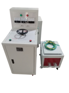
Click the image to know more about 6000A Primary Current Injection Tester.
How Do You Calculate Circuit Breaker Primary Injection Test Current?
When a test procedure specifies a current multiple, calculate the target current using:
Target current = Reference current × Test multiple
The reference current may be a specified pickup setting or another value defined by the applicable procedure. Engineers must not automatically use the breaker’s rated current as the reference for every protection function.
For example, assume a documented pickup setting of 400 A and an approved procedure requiring 1.5 times that setting.
[
400\text{ A}\times1.5=600\text{ A}
]
The target current is 600 A. This is a calculation example, not a universal test requirement for a 400 A circuit breaker.
Should You Use the Breaker’s Rated Current or Trip Pickup Setting?
The correct reference depends on the protection function and the test procedure. The rated current and the trip pickup setting are not always the same.
For a breaker with an adjustable electronic trip unit, the long-time pickup may be configured below the rated current of the breaker frame. Short-time and instantaneous protection may use different settings or current thresholds.
| Reference value | Meaning | When it may be relevant |
|---|---|---|
| Rated current | The breaker or trip-unit current rating as defined by the manufacturer | Identifying the equipment and interpreting its rating |
| Long-time pickup | The configured threshold for long-time overload protection | Testing the specified long-time function |
| Short-time pickup | The configured threshold for short-time protection | Testing short-time response where provided |
| Instantaneous pickup | The configured threshold for instantaneous protection | Testing instantaneous operation where provided |
| Ground-fault pickup | The configured ground-fault threshold where available | Testing the specified ground-fault function |
Use the value required by the manufacturer’s procedure. Do not calculate every test current from the nameplate rating alone.
How Do You Calculate a Test Current Multiple?
The current multiple expresses the applied current relative to a defined reference current.
Test multiple = Applied current ÷ Reference current
For example, if the reference pickup setting is 400 A and the actual injected current is 800 A:
[
800\text{ A}\div400\text{ A}=2
]
The applied current is 2 times the reference setting.
The report should state the reference value used. Without that information, the current multiple can be misleading because the same injected current may represent different multiples for different trip settings.
How Do You Estimate the Required Test Voltage?
The injection tester must provide sufficient voltage to drive the target current through the complete test circuit.
For a predominantly resistive circuit, Ohm’s law gives:
V = I × R
For example, if the total circuit resistance is 2 mΩ and the target current is 1,000 A:
[
V=1000\text{ A}\times0.002\ \Omega=2\text{ V}
]
The theoretical resistive voltage drop is 2 V. Actual requirements may be higher because the complete circuit includes test leads, connections, and potentially inductive impedance.
This calculation is useful for preliminary planning, but it does not replace the manufacturer’s current-voltage characteristics. Confirm the expected current under the actual connection conditions before testing.
Why Might the Actual Injection Current Be Lower Than the Target?
The tester may be unable to deliver the target current if the circuit requires more output voltage than the instrument can provide. Cable resistance, poor connections, and excessive circuit impedance can all affect the result.
| Observation | Possible factor to investigate |
|---|---|
| Current remains below the target | Insufficient output voltage for the circuit impedance |
| Current changes when connections move | Loose or unstable connections |
| Cables or terminals become hot | Excessive resistance, inadequate conductor rating, or excessive duration |
| Tester output reaches its limit | The circuit demand exceeds the available output capability |
| Current varies between repeated tests | Changes in connections, supply conditions, or equipment temperature |
These symptoms are diagnostic clues rather than proof of a specific fault. Stop the test if an unsafe condition develops and follow the approved troubleshooting procedure.
How Do You Measure Circuit Breaker Trip Time?
Trip time is the elapsed time between the defined start of the test current and the specified trip event. Engineers should record both the applied current and the measured time.
The expected time depends on the protection function, current multiple, trip settings, and manufacturer’s time-current characteristics. Long-time protection generally operates on a different timescale from instantaneous protection, so a single universal time limit is not appropriate.
Use the timing method and acceptance criteria defined by the test procedure. If the trip unit has configurable delays, record the relevant settings with the measurement.
How Do You Interpret a Circuit Breaker Trip Time Curve?
A time-current curve shows the expected relationship between current and operating time under the manufacturer’s specified conditions. Engineers use the curve to assess whether the measured response is consistent with the configured protection function.
For a particular injected current, identify the relevant portion of the curve and account for the applicable tolerance band. Compare the measured result with the correct curve for the breaker model and trip settings.
Do not compare the result against a curve from a different trip unit or configuration. If the manufacturer’s curve includes separate bands or tolerances, use the applicable limits rather than reading a single nominal time as an absolute pass/fail boundary.
How Should Engineers Choose Test Points for Different Trip Functions?
The test points must come from the approved test procedure and the protection settings being verified. They should be selected to evaluate the required functions while respecting the equipment’s thermal limits and the injection system’s duty cycle.
| Protection function | Test-point consideration | Result to record |
|---|---|---|
| Long-time | Defined overload current and permitted duration | Actual current and operating time |
| Short-time | Configured pickup and delay characteristics | Actual current and response time |
| Instantaneous | Required current relative to the configured threshold | Actual current and trip response |
| Ground-fault | Prescribed current path and pickup conditions | Actual test arrangement and response |
This table describes what to consider, not mandatory current multiples. Exact values must be obtained from the manufacturer or the approved procedure.
What Information Should Be Included in the Test Calculation Record?
A calculation record should identify the breaker, trip-unit settings, reference current, current multiple, target current, and actual measured current. Include the source of the test requirement, such as a manufacturer’s procedure or project specification.
Record the measured trip time and the acceptance criteria separately. This makes it possible for another engineer to reproduce the calculation and verify the pass/fail decision.
How Can a Primary Current Injection Tester Support Accurate Testing?
The tester must deliver the required current through the actual circuit impedance for the specified duration. Its output rating, cable arrangement, and measurement capability should be checked before the test begins.
The Wrindu RDSL-82-6000D Primary Current Injection Tester is designed for high-current injection applications. Confirm its rated output voltage, current range, duty cycle, and measurement specifications before using it for a particular circuit breaker test.
Accurate test calculations and suitable equipment selection work together. Neither a calculated target current nor a maximum current rating alone proves that a test setup is suitable.
