

How Is Primary Injection Testing Used for Current Transformers?
Learn how CT primary injection testing checks current ratio, secondary response, wiring, and polarity, with calculation examples and safety precautions.
Current transformer (CT) primary injection testing applies a known current to the CT primary circuit and measures the resulting secondary current. Engineers use the measurements to check the current transformation relationship and investigate selected wiring or installation problems.
The test requires a suitable current source, a defined primary current path, and an appropriate secondary measurement arrangement. Results depend on the CT ratio, test current, connection configuration, instrument accuracy, and test conditions.
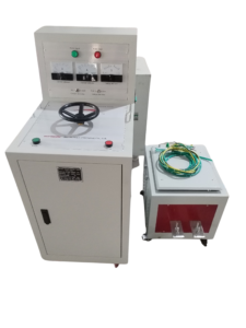
Click the image to know more about 6000A Primary Current Injection Tester.
What Is the Purpose of CT Primary Injection Testing?
A CT converts a primary current into a smaller secondary current according to its nominal transformation ratio. Primary injection testing checks the response of the installed CT circuit when current passes through the primary path.
The test can help identify incorrect wiring, an unexpected secondary response, or a mismatch between the measured and expected current relationship. It may also support commissioning checks of metering or protection circuits.
However, a primary injection test alone does not establish the CT’s complete accuracy performance. Accuracy class, phase displacement, burden, and other characteristics may require additional tests using the applicable CT test method.
How Do You Calculate the Expected CT Secondary Current?
The nominal CT ratio relates primary current to secondary current. For a CT rated 1000/5 A, the nominal ratio is 200:1.
The expected secondary current can be estimated using:
Iₛ = Iₚ × (Iₛₙ / Iₚₙ)
Where:
- (I_s) = expected secondary current
- (I_p) = applied primary current
- (I_{sn}) = rated secondary current
- (I_{pn}) = rated primary current
For example, consider a 1000/5 A CT with a primary test current of 200 A.
[
I_s = 200 \times \frac{5}{1000} = 1\text{ A}
]
The nominal expected secondary current is 1 A, assuming the CT and measurement circuit operate under suitable test conditions. The actual reading may differ because of measurement uncertainty, CT characteristics, and the connected burden.
What Equipment Is Needed for CT Primary Injection Testing?
The required equipment depends on the CT rating, installation, and test procedure. A typical setup includes the following items.
| Equipment | Purpose | Key consideration |
|---|---|---|
| Primary current injection tester | Supplies current to the primary circuit | Must deliver the target current under the actual circuit impedance |
| Current measurement instrument | Measures the applied primary current | Must cover the required current range |
| Secondary current measurement instrument | Measures CT secondary current | Must suit the CT output and required accuracy |
| Test cables and connectors | Complete the primary injection circuit | Must be rated for the intended current and duration |
| Test leads and terminals | Connect secondary measurement equipment | Must be correctly identified and secured |
| Approved test procedure | Defines connections and acceptance criteria | Must match the CT and installation |
The instrument ratings should be checked before testing. A tester rated for a particular maximum current may deliver less current if the total circuit impedance is too high.
How Do Engineers Perform a CT Primary Injection Test?
The following steps describe a general approach. The actual procedure must follow the CT manufacturer’s instructions and the approved site test plan.
Step 1: Identify the CT.
Record the CT nameplate ratio, rated secondary current, terminal markings, and intended application. Check the approved drawings to identify the primary and secondary circuits.
Step 2: Review the test arrangement.
Confirm the required test current, the current path, the measuring instruments, and the expected result. Establish the necessary isolation and work controls before making connections.
Step 3: Prepare the secondary circuit.
Identify the connected relays, meters, and test terminals. Follow the approved procedure for isolating or including secondary equipment in the test.
Step 4: Connect the primary injection circuit.
Connect the current source to the specified primary path. Ensure that cables, connectors, and return paths are secure and rated for the test current.
Step 5: Measure both currents.
Apply the specified current and record the actual primary current and the corresponding secondary current. Use instruments with suitable ranges and documented measurement accuracy.
Step 6: Compare the measured ratio.
Calculate the measured current ratio and compare it with the nominal CT ratio and the acceptance criteria. Investigate unexpected results before concluding that the CT circuit is acceptable.
Step 7: Restore the circuit.
Remove test connections and restore secondary wiring, protection circuits, and isolation links according to the approved procedure. Verify the final configuration before returning the equipment to service.
How Do Engineers Compare the Measured and Nominal CT Ratios?
The nominal ratio is calculated from the rated primary and secondary currents. The measured ratio is calculated from the primary and secondary currents recorded during the test.
[
\text{Measured ratio}=\frac{I_p}{I_s}
]
For a nominal 1000/5 A CT, the expected ratio is 200:1. If the measured primary current is 200 A and the secondary current is 0.98 A, the measured ratio is approximately 204.1:1.
This difference should not automatically be classified as a CT failure. Engineers must consider instrument accuracy, the test configuration, the CT’s operating conditions, and the acceptance criteria specified for the test.
A ratio check during primary injection is a practical installation check, but it does not replace a complete accuracy test when that test is required.
Can Primary Injection Testing Verify CT Polarity?
Primary injection can help check polarity when the test arrangement includes suitable instruments and a defined polarity procedure. The test must use the correct terminal references and measurement method.
Simply measuring the magnitude of primary and secondary current does not establish polarity. A separate polarity check or an approved method that identifies the relationship between primary and secondary directions may be necessary.
The report should state which polarity method was used and what was observed. Do not claim polarity verification when only current magnitudes were recorded.
What Safety Precautions Are Required During CT Primary Injection Testing?
Primary injection can produce high currents and significant heating at conductors and connections. Engineers should verify cable ratings, connection tightness, test duration, and the injection system’s operating limits before applying current.
CT secondary circuits require particular care. When primary current is flowing, an energized CT secondary must not be left open-circuited unless the specific approved procedure and CT design explicitly permit it; open-circuit conditions can produce hazardous secondary voltages.
Follow the approved isolation and secondary-circuit handling procedure. Never disconnect a CT secondary under load without the required controls and authorization.
Which Standards Apply to Current Transformer Testing?
IEC 61869-2 covers additional requirements for current transformers within the IEC 61869 instrument-transformer series. IEEE C57.13 covers requirements for instrument transformers within its scope.
The appropriate standard and test procedure depend on the CT type, application, and acceptance requirement. A field primary injection check is not automatically equivalent to a factory accuracy test or every verification specified by an instrument-transformer standard.
Before testing, confirm the applicable edition, the manufacturer’s instructions, and the project requirements. Use the specified acceptance criteria rather than applying a generic ratio tolerance to every CT.
How Do You Choose a Primary Injection Tester for CT Testing?
The required output current depends on the CT rating and the test objective. Some installation checks require only a fraction of the CT’s rated primary current, while other procedures may require a higher current.
Choose a tester that can deliver the required current through the complete circuit for the specified duration. Also consider the available output voltage, cable arrangement, measurement equipment, and site power supply.
The Wrindu RDSL-82-6000D Primary Current Injection Tester is intended for high-current injection applications in substations, power plants, laboratories, and electrical equipment manufacturing facilities. Confirm the model’s output range and current-voltage characteristics before using it for a particular CT test.
What Information Should a CT Primary Injection Test Report Include?
A useful report records the CT identification, nameplate ratio, test connections, injected primary current, measured secondary current, calculated ratio, and acceptance criteria.
If polarity was tested, record the method and result separately. Document any abnormal readings, connection issues, or deviations from the approved procedure so that another engineer can review the evidence.
Clear records help distinguish a current-ratio check from a complete CT accuracy assessment. They also support comparison with future commissioning or maintenance results.
