

How Is Primary Injection Testing Used for Earth Fault Protection?
Learn how primary injection testing verifies earth fault CTs, residual current detection, protection relay pickup, and trip circuit operation.
Earth fault protection detects abnormal current flowing from an energized conductor to earth. Primary injection testing helps engineers verify whether the protection system detects the injected fault current and operates as required.
The test applies current through a selected primary circuit. It can help check current transformers (CTs), earth fault detection circuits, and associated protection operation.
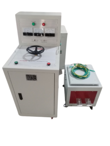
Click the image to know more about 6000A Primary Current Injection Tester.
What Is Earth Fault Protection in an Electrical System?
Earth fault protection detects current caused by an unintended connection between an energized conductor and earth or grounded equipment.
When an earth fault occurs, the current distribution in the electrical system changes. A protection relay detects the residual or earth fault current and sends a trip command when the measured value meets its operating conditions.
Common applications include:
- Distribution switchgear.
- Power transformers.
- Industrial motor circuits.
- Generator protection systems.
- Medium-voltage distribution networks.
The protection arrangement depends on the system grounding method and the selected CT configuration.
How Does Primary Injection Testing Check Earth Fault Protection?
Primary injection testing applies a controlled current through the primary circuit to simulate a current condition that the earth fault protection system should detect.
For a core balance current transformer (CBCT), engineers can pass a test conductor through the CT aperture and arrange the return conductor outside the aperture. This creates an imbalance in the current detected by the CT.
The relay receives the resulting secondary signal and can be checked for pickup and trip operation.
For residual protection using separate phase CTs, the injection arrangement must reproduce the intended residual current condition. The exact connection depends on the protection design.
Which Components Are Checked During Earth Fault Protection Testing?
The test can cover several parts of the protection arrangement, depending on the injection method.
| Component | Testing objective |
|---|---|
| Core balance CT | Check response to residual current |
| Phase CTs | Check current detection in the selected arrangement |
| Earth fault relay | Verify pickup and associated protection response |
| Trip circuit | Check the trip command path when included |
| Circuit breaker | Confirm operation following a valid trip command |
Primary injection can verify parts of the installed protection path. It does not automatically confirm every relay setting, logic function, or circuit breaker operating characteristic.
What Is the Difference Between Residual Current and Core Balance CT Testing?
Both methods can support earth fault protection verification, but their test arrangements differ.
| Comparison | Residual current detection | Core balance CT detection |
|---|---|---|
| Current measurement | Uses the sum of phase CT secondary currents | Measures the magnetic imbalance around conductors passing through the CT |
| Typical arrangement | Separate CTs on phase conductors | One CT surrounding the relevant conductors |
| Fault indication | Non-zero residual current | Non-zero residual current |
| Test consideration | Correct CT polarity and secondary connections | Correct conductor routing through the CT aperture |
For a balanced three-phase system, the vector sum of the phase currents is approximately zero. An earth fault can create a residual current that the protection system detects.
How Do Engineers Evaluate Earth Fault Protection Test Results?
Engineers should compare the measured response with the approved protection settings and equipment requirements.
Important test records include:
| Test item | Information to record |
|---|---|
| Injection current | Actual primary current in amperes |
| CT response | Secondary current or residual current |
| Relay pickup | Current at which the relay operates |
| Operating time | Time between the defined test start and relay operation |
| Trip response | Whether the trip command operates the intended circuit |
| Test configuration | CT type and injection connection |
The pickup current and operating time must be evaluated against the actual relay settings and approved coordination requirements. There is no universal earth fault pickup value for all electrical systems.
Can Primary Injection Testing Verify the Complete Earth Fault Protection System?
The answer depends on the test arrangement.
A properly designed primary injection test can check the primary current path, CT response, and associated relay operation. If the test includes the trip circuit and circuit breaker, it can also verify the corresponding trip response.
However, some protection functions require additional testing. Secondary injection may be needed to verify individual relay settings, timing characteristics, and logic functions that primary injection does not fully cover.
Engineers should combine the required tests according to the protection design and commissioning procedure.
What Equipment Is Used for Earth Fault Primary Injection Testing?
A primary current injection tester supplies the current needed to test the selected primary circuit.
The Wrindu RDSL-82-6000D Primary Current Injection Tester provides up to 6000 A output current and has a rated capacity of 36 kVA.
| Parameter | Specification |
|---|---|
| Model | RDSL-82-6000D |
| Maximum output current | 6000 A |
| Rated capacity | 36 kVA |
| Output voltage | 6 V |
| Structure | Split-type |
| Current monitoring | Two ammeters |
| Power-on time | Less than 2.5 minutes |
| Working cycle | Longer than 10 minutes |
The required output current depends on the CT configuration, relay settings, and test objective. Engineers must also consider the complete test circuit impedance.
Explore the Wrindu RDSL-82-6000D Primary Current Injection Tester.
What Should Engineers Check Before Earth Fault Protection Testing?
Before starting the test, engineers should identify the protection arrangement and confirm the correct injection connection.
Important checks include:
- Identify the CT type and location.
- Confirm CT polarity and secondary wiring.
- Check the earth fault relay settings.
- Determine the required test current.
- Confirm the injection and return current paths.
- Verify the trip circuit configuration.
- Follow the equipment manufacturer’s safety instructions.
A correct test arrangement helps prevent incorrect conclusions about earth fault protection performance.
