

Why Does a Protection Relay Trip Unexpectedly During Primary Injection Testing?
Find out why protection relays trip unexpectedly during primary injection testing and how to check relay settings, CT circuits, and protection zones.
A protection relay may trip unexpectedly during primary current injection testing when the injected current activates a protection function or creates an unintended operating condition.
The cause may be related to the protection settings, CT wiring, current direction, protection zone, or test connection. Engineers should identify which protection function operated before changing the test arrangement.
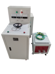
Click the image to know more about 6000A Primary Current Injection Tester.
Why Can Primary Injection Testing Cause an Unexpected Relay Trip?
Primary injection testing sends current through an installed primary circuit. The resulting CT secondary signals can reach connected protection relays.
If the measured current satisfies a relay’s operating conditions, the relay may issue an alarm or trip command.
Possible causes include:
- The injected current exceeds a protection pickup setting.
- The test current enters an unintended protection zone.
- The current direction activates a directional protection function.
- The test arrangement creates residual current.
- The injection path affects multiple connected protection circuits.
An unexpected trip does not automatically mean the relay is defective. It may be responding correctly to the applied current.
Which Protection Functions May Operate During Primary Injection Testing?
Different protection functions respond to different electrical conditions.
| Protection function | Possible reason for operation |
|---|---|
| Overcurrent protection | Injected current exceeds the configured pickup value |
| Earth fault protection | Residual current reaches the operating threshold |
| Differential protection | Current balance within the protected zone changes |
| Directional overcurrent protection | Current direction and magnitude meet the operating conditions |
| Undervoltage protection | Test conditions affect the monitored voltage input |
| Thermal overload protection | The test current and duration meet the relay’s thermal operating model |
Not all these functions are directly activated by primary current injection. Some also depend on voltage inputs, relay logic, or additional simulated signals.
How Can Engineers Identify Which Relay Function Caused the Trip?
The first step is to review the relay event record or trip indication.
Modern protection relays may record the operating element, measured current, event time, and trip output status.
Engineers should check:
- The relay alarm and trip indicators.
- The event or disturbance record.
- The protection element that operated.
- The measured phase or residual current.
- The relay settings active during the test.
The recorded operating element helps narrow down the possible cause. Engineers should not reset the relay before preserving relevant event information.
Can an Incorrect Test Connection Activate Another Protection Zone?
Yes. An injection path that does not match the approved test arrangement may introduce current into another monitored circuit.
This can happen in systems with multiple CTs, interconnected feeders, or several protection zones.
For example, a test current applied through a shared conductor may affect more than one CT or protection input. The resulting relay response may therefore differ from the expected response of the selected circuit.
Engineers should review the single-line diagram, CT locations, and protection zone drawings before injection.
How Does Protection Pickup Setting Affect Unexpected Trips?
A protection relay operates according to its configured settings and operating characteristics.
If the injected current exceeds the pickup threshold, the relay may start its operating sequence.
For example, if an overcurrent element has a pickup setting of 5 A secondary and the measured relay input reaches 6 A, the element may operate according to its configured timing characteristic.
This is an illustrative example, not a recommended setting.
Engineers must use the actual relay settings and CT transformation ratio when determining the expected primary injection current.
Should Engineers Disable Protection Relays Before Primary Injection Testing?
Protection functions should never be disabled without an approved test and safety plan.
Some commissioning procedures require temporary isolation of selected trip outputs to prevent unintended operation of connected equipment. Other procedures require the complete trip circuit to remain included in the test.
The correct arrangement depends on the test objective and site protection requirements.
Engineers should obtain authorization, identify the protection functions affected, and document any temporary changes. All protection functions must be restored and verified before returning the equipment to service.
How Can Engineers Prevent Unwanted Trips During Testing?
Preparation should focus on the protection zone, injection path, and expected relay response.
| Check | Purpose |
|---|---|
| Review protection settings | Identify current and timing thresholds |
| Review CT connections | Confirm the intended current measurement path |
| Check protection zone drawings | Avoid unintended current injection into another zone |
| Confirm test isolation | Prevent unintended operation of connected equipment |
| Review trip circuit arrangements | Understand which devices may operate |
| Record relay events | Preserve evidence of unexpected operation |
A test plan should define which protection elements are expected to operate and which trip outputs must be included.
What Should Engineers Do After an Unexpected Relay Trip?
Engineers should stop the test safely and preserve the relay event records.
They should then compare the actual current, operating element, and injection connection with the approved test plan.
The test should only resume after the cause has been understood and the test arrangement has been checked. Repeatedly injecting current without identifying the cause may result in unnecessary equipment operation.
How Does Wrindu Support Primary Injection Testing Applications?
Wrindu supplies primary current injection testers for electrical testing, commissioning, and maintenance applications.
The RDSL-82-6000D provides up to 6000 A output current, a rated capacity of 36 kVA, and a 6 V output rating.
Its short-time and intermittent operating design specifies a power-on time of less than 2.5 minutes and a working cycle longer than 10 minutes.
View the Wrindu RDSL-82-6000D Primary Current Injection Tester.
