

How Do You Perform Primary Injection Testing on MCCB and ACB Circuit Breakers?
Learn how to test MCCB and ACB trip functions using primary current injection, including protection settings, trip timing, and result evaluation.
Primary injection testing checks selected circuit breaker protection functions by passing a controlled current through the main current path. Engineers use this method to evaluate whether the breaker responds according to its trip settings and the manufacturer’s time-current characteristics.
Molded-case circuit breakers (MCCBs) and air circuit breakers (ACBs) may use different trip mechanisms and protection settings. The test procedure must match the breaker design, trip unit, and required acceptance criteria.
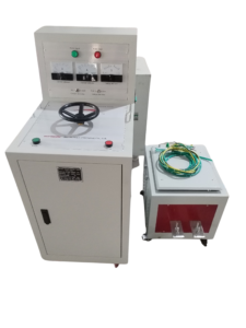
Click the image to know more about 6000A Primary Current Injection Tester.
What Is the Difference Between MCCB and ACB Primary Injection Testing?
MCCBs are commonly used in distribution circuits, while ACBs are often used in larger low-voltage distribution systems. Their rated currents, trip mechanisms, and available protection functions vary by model.
| Item | MCCB | ACB |
|---|---|---|
| Full name | Molded-case circuit breaker | Air circuit breaker |
| Typical application | Distribution feeders, panels, and branch circuits | Main incoming feeders, bus couplers, and high-current distribution |
| Trip mechanism | Thermal-magnetic or electronic, depending on model | Often electronic on modern models, depending on configuration |
| Possible test functions | Overload and instantaneous protection; other functions where provided | Long-time, short-time, instantaneous, and ground-fault protection where provided |
| Test requirements | Manufacturer’s procedure and trip characteristics | Trip-unit settings, available functions, and manufacturer procedures |
These are general distinctions, not universal specifications. Engineers must check the actual breaker nameplate and trip-unit documentation before preparing a test.
Which Protection Functions Can Be Checked by Primary Injection Testing?
The functions available for testing depend on the breaker and its trip unit. A test should identify the specific protection function being evaluated.
| Protection function | Purpose | What the test evaluates |
|---|---|---|
| Long-time protection | Responds to sustained overload current | Trip response under the specified overload condition |
| Short-time protection | Provides delayed response to higher overcurrent levels where fitted | Operation at the specified current and delay setting |
| Instantaneous protection | Responds to sufficiently high current with minimal intentional delay | Whether the expected trip response occurs |
| Ground-fault protection | Detects specified ground-fault conditions where provided | Response under the manufacturer’s prescribed test arrangement |
Not every breaker includes all four functions. Ground-fault protection also requires an appropriate test arrangement; injecting current through an arbitrary conductor path may not correctly test the intended function.
How Should Engineers Prepare an MCCB or ACB for Primary Injection Testing?
First, identify the breaker model, rated current, trip-unit type, and protection settings. Obtain the applicable time-current curves and the manufacturer’s test instructions.
Next, define the target current, expected trip response, test duration, and acceptance criteria for each test point. Confirm that the injection tester, cables, connectors, and measurement instruments can handle the required current.
The breaker and test circuit must be placed in the required safe condition. Follow the site’s approved isolation, lockout/tagout, and verification procedures before making connections.
How Do You Connect a Primary Current Injection Tester to an MCCB or ACB?
Connect the tester to the prescribed primary current path using the manufacturer’s specified test arrangement. The connection must allow the intended current to pass through the relevant breaker poles or conductors.
Before applying current, verify that the cables and terminals are correctly rated and securely connected. Loose or undersized connections can cause excessive heating and unstable test current.
The exact connection method varies by breaker design. Do not assume that a test arrangement suitable for one MCCB or ACB is suitable for another model.
How Do You Test Long-Time, Short-Time, and Instantaneous Protection?
Each protection function requires its own test conditions. The current level and permitted response time must come from the manufacturer’s trip characteristics or the approved test specification.
For long-time protection, engineers assess the breaker response to a specified overload condition. The test duration may be longer than that required for short-time or instantaneous testing, so the breaker’s thermal limits and the test equipment’s duty cycle must be considered.
For short-time protection, the test must account for the selected pickup and delay settings. For instantaneous protection, the applied current must be appropriate for the configured pickup threshold and the manufacturer’s prescribed procedure.
Do not apply one generic current multiple or trip-time limit to all three functions. Record the actual injected current and measured trip time for every test point.
How Do Engineers Test Ground-Fault Protection on an MCCB or ACB?
Ground-fault protection testing requires a test arrangement that produces the correct electrical condition for the specific trip unit. The appropriate method depends on the breaker design, sensing arrangement, and manufacturer’s instructions.
A simple current injection through one pole does not necessarily verify the complete ground-fault protection function. Engineers should confirm the required current path, sensor response, pickup setting, and trip criteria before testing.
Where the ground-fault function uses external sensors or additional control circuits, those components must be included or tested according to the approved procedure. Document the arrangement so that the result can be interpreted correctly.
How Do You Evaluate MCCB and ACB Trip Test Results?
Compare the measured trip response with the manufacturer’s time-current characteristics and the acceptance criteria for the specific protection function. The comparison must use the actual current and relevant trip settings.
| Recorded item | Why it matters |
|---|---|
| Breaker model and rated current | Identifies the equipment under test |
| Trip-unit type and settings | Defines the expected protection response |
| Injected current | Establishes the actual test condition |
| Trip time | Shows the measured response |
| Protection function | Identifies which function was tested |
| Acceptance criteria | Provides the basis for pass/fail assessment |
| Test result | Records compliance or the need for further investigation |
A successful test of one function does not establish that all other protection functions operate correctly. Each required function must be assessed separately.
Which Standards Apply to MCCB and ACB Testing?
IEC 60947-2:2024 covers low-voltage circuit breakers within its stated scope, including equipment for circuits up to 1,000 V AC or 1,500 V DC.
The applicable standard and test procedure depend on the breaker, the test objective, and the project requirements. A field primary injection test should not automatically be treated as equivalent to every verification required by a product standard.
Engineers should confirm the applicable standard edition, manufacturer’s instructions, and commissioning or maintenance specification before approving the test procedure.
Which Primary Current Injection Tester Should Engineers Use for MCCB and ACB Testing?
Select a tester based on the highest required current, circuit impedance, test duration, and the measurement requirements of the planned tests. A higher maximum current rating does not guarantee that the tester can deliver the target current through every connection arrangement.
The Wrindu RDSL-82-6000D Primary Current Injection Tester is intended for high-current testing in substations, power plants, laboratories, and electrical equipment manufacturing facilities. Before using it for a particular MCCB or ACB, confirm its rated output characteristics, duty cycle, cable requirements, and compatibility with the test procedure.
A suitable test setup must meet both the electrical requirements and the safety requirements of the application.
