

How to Perform a Ground Resistance Test Step by Step: Complete Field Testing Guide
Learn how to perform a ground resistance test step by step, including test preparation, electrode placement, measurement procedures, common mistakes, and accuracy improvement tips.
What Is the Purpose of Performing a Ground Resistance Test?
A ground resistance test is performed to evaluate whether an electrical grounding system can safely discharge fault current into the earth.
The main purpose of this test is to verify that the grounding system provides a reliable low-resistance path during abnormal electrical conditions.
A properly tested grounding system helps protect:
- Electrical equipment
- Power system infrastructure
- Maintenance personnel
- Industrial operations
Ground resistance testing is commonly performed in:
- Power substations
- Transformer installations
- Industrial facilities
- Renewable energy projects
- Commercial electrical systems
Regular testing also helps identify grounding problems before they develop into serious safety risks.
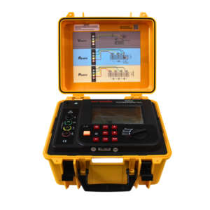
Click the picture to know more about Wrindu Earth Resistance Tester.
What Equipment Is Needed for a Ground Resistance Test?
Before starting a test, engineers need to prepare suitable testing equipment and accessories.
What Is a Ground Resistance Tester?
A ground resistance tester is the main instrument used to measure the resistance between a grounding system and the earth.
A professional tester typically provides:
- Controlled test current output
- Voltage measurement capability
- Automatic resistance calculation
- Data storage functions
- Interference reduction technology
What Accessories Are Required for Testing?
A typical ground resistance test requires:
- Ground resistance tester
- Test cables
- Current electrode
- Potential electrode
- Test electrode connection
- Measuring tape
- Ground rods
The quality and condition of these accessories can directly affect measurement accuracy.
What Should Be Checked Before Performing a Ground Resistance Test?
Proper preparation helps reduce measurement errors.
How Should the Grounding System Be Inspected Before Testing?
Before measurement:
- Check grounding conductor condition
- Inspect connection points
- Confirm test location
- Review grounding system design if available
Damaged connections or corrosion may influence the final test result.
Should the Grounding System Be Disconnected Before Testing?
In some applications, the grounding electrode should be disconnected from parallel grounding paths.
This prevents other grounding connections from affecting the measurement.
However, the correct procedure depends on:
- System design
- Safety requirements
- Testing standards
How Do You Perform a 3-Point Ground Resistance Test Step by Step?
The 3-point fall-of-potential method is one of the most common procedures for accurate grounding resistance measurement.
Step 1: Select the Test Location
Choose a suitable location around the grounding electrode.
The area should allow enough space for installing auxiliary electrodes.
Avoid locations near:
- Underground cables
- Large electrical equipment
- Strong electromagnetic interference sources
Step 2: Install the Test Electrode Connection
Connect the ground resistance tester to the grounding system under test.
The connection should be:
- Clean
- Tight
- Electrically stable
A poor connection can create unstable readings.
Step 3: Place the Current Electrode
The current electrode creates the path for test current flow through the soil.
During testing:
- Current flows from the grounding system to the current electrode.
- The tester measures the response of the earth resistance path.
The current electrode should be placed far enough away to avoid overlapping resistance areas.
Step 4: Place the Potential Electrode
The potential electrode measures voltage drop between the grounding system and the earth.
A common guideline is to place it at approximately:
62% of the distance between the test electrode and current electrode
Correct positioning is important because incorrect placement may cause inaccurate readings.
Step 5: Connect Test Leads Correctly
Connect the tester terminals:
- E or X terminal → Grounding electrode under test
- P terminal → Potential electrode
- C terminal → Current electrode
Check all connections before starting measurement.
Step 6: Apply Test Current and Measure Resistance
The tester injects a controlled AC current into the soil.
The instrument measures:
- Test current
- Voltage drop
Using Ohm’s Law:
R = V / I
the tester calculates the ground resistance value automatically.
Step 7: Verify Measurement Stability
After obtaining a reading, engineers should confirm the result is reliable.
Important checks include:
- Stable measurement value
- Correct electrode arrangement
- Repeatable results
For critical systems, additional measurements may be performed by moving the potential electrode position.
How Can You Improve Ground Resistance Test Accuracy?
Accurate measurement depends on proper testing techniques and environmental conditions.
Why Is Correct Electrode Spacing Important?
Each electrode creates a resistance area in the surrounding soil.
If electrodes are too close:
- Resistance zones overlap.
- The tester may not measure the true grounding resistance.
Proper spacing allows accurate evaluation of the grounding system.
How Does Soil Condition Affect Test Accuracy?
Soil characteristics directly influence grounding resistance.
Important factors include:
- Moisture content
- Soil composition
- Temperature
- Seasonal changes
For example:
Wet soil usually produces lower resistance values, while dry soil may increase resistance.
How Does Test Cable Quality Affect Results?
Damaged or poor-quality cables may introduce measurement errors.
Before testing:
- Check cable insulation
- Confirm cable connections
- Avoid unnecessary cable contact with metal objects
What Are Common Problems During Ground Resistance Testing?
Why Are Ground Resistance Readings Unstable?
Unstable readings may result from:
- Poor electrode contact
- Electrical interference
- Incorrect connections
- Changing soil conditions
Solutions include:
- Checking all connections
- Improving electrode contact
- Moving test locations if necessary
Why Are Ground Resistance Results Too High?
High resistance readings may be caused by:
- Dry soil
- Corroded electrodes
- Poor grounding design
- Loose connections
Engineers should inspect the grounding system before deciding whether the result indicates a real problem.
Why Are Ground Resistance Results Different From Previous Tests?
Changes may occur because of:
- Seasonal soil changes
- Grounding system aging
- Environmental conditions
- Different test locations
Comparing historical data helps determine whether performance is degrading.
What Are the Different Ground Resistance Testing Methods?
3-Point Fall-of-Potential Method
The 3-point method is commonly used for accurate measurement of installed grounding systems.
Applications:
- Substations
- Transformers
- Industrial grounding networks
4-Point Soil Resistivity Method
The 4-point method evaluates soil characteristics before grounding system design.
Applications:
- New substations
- Solar farms
- Large industrial projects
Clamp-On Ground Resistance Testing
Clamp testing allows measurement without disconnecting grounding conductors.
Advantages:
- Fast testing
- Simple operation
- Suitable for maintenance inspections
However, it requires a complete grounding loop to work correctly.
How Often Should Ground Resistance Testing Be Performed?
Testing frequency depends on:
- Local regulations
- Equipment importance
- Environmental conditions
- Industry requirements
When Should New Installations Be Tested?
New grounding systems should be tested before electrical equipment is energized.
When Should Existing Systems Be Tested?
Routine testing is recommended during:
- Preventive maintenance
- Electrical inspections
- System upgrades
Should Grounding Systems Be Tested After Lightning Events?
Yes.
Lightning events may damage:
- Grounding conductors
- Ground electrodes
- Connection points
Testing confirms whether the grounding system remains effective.
What Industries Use Ground Resistance Testing?
Power Utilities
Utilities use grounding tests for:
- Transmission systems
- Distribution networks
- Substations
Reliable grounding is essential for high-voltage safety.
Industrial Manufacturing
Factories test grounding systems to protect:
- Motors
- Control systems
- Production equipment
Renewable Energy Facilities
Solar and wind power projects require grounding tests for:
- Lightning protection
- Equipment safety
- Electrical reliability
Construction and Engineering Projects
Contractors use grounding tests to verify electrical installation quality before operation.
How Does Wrindu Support Ground Resistance Testing?
Wrindu provides professional electrical testing solutions designed for power utilities, industrial companies, and engineering organizations.
Wrindu ground resistance testing equipment helps engineers achieve:
- Accurate measurement results
- Reliable field operation
- Efficient testing procedures
- Improved grounding system maintenance
With practical designs and reliable performance, Wrindu supports safe and efficient grounding evaluation in different electrical environments.
Frequently Asked Questions About Ground Resistance Testing Procedures
What Is the First Step in a Ground Resistance Test?
The first step is preparing the testing area, inspecting the grounding system, and selecting the correct test location.
How Long Does a Ground Resistance Test Take?
The testing time depends on:
- Grounding system size
- Soil conditions
- Testing method
- Field environment
A simple test may take several minutes, while large grounding systems require more time.
Where Should the Potential Electrode Be Placed?
The potential electrode is commonly placed at approximately 62% of the distance between the test electrode and current electrode.
Can Ground Resistance Testing Be Performed Without Disconnecting the Grounding System?
Some testing methods, such as clamp-on measurement, can be performed without disconnecting grounding conductors.
Traditional 3-point testing may require isolation depending on the system configuration.
Why Is My Ground Resistance Reading Too High?
Possible causes include:
- High soil resistivity
- Poor electrode contact
- Corrosion
- Grounding system problems
What Is the Most Accurate Ground Resistance Testing Method?
The 3-point fall-of-potential method is widely considered one of the most accurate methods for measuring installed grounding resistance when performed correctly.
Can Ground Resistance Testing Be Used for Transformers?
Yes.
Transformer grounding systems are commonly tested to verify safe operation and fault current discharge capability.
What Is the Difference Between Ground Resistance Testing and Continuity Testing?
Continuity testing checks whether an electrical connection exists, while ground resistance testing measures the actual resistance between the grounding system and earth.
Conclusion
Performing a ground resistance test correctly requires proper preparation, accurate electrode placement, reliable testing equipment, and careful result evaluation.
The 3-point fall-of-potential method remains one of the most widely used approaches for verifying grounding system performance.
By following correct testing procedures and performing regular inspections, engineers can identify grounding problems early, improve electrical safety, and maintain reliable operation of power and industrial systems.
