

How to Use a Micro-Ohmmeter for Transformer Winding and Contact Resistance Testing
Learn how to use a micro-ohmmeter for transformer winding and contact resistance testing. Understand Kelvin connections, test currents, measurement methods, and fault analysis.
Reliable electrical connections are essential for the safe operation of transformers, circuit breakers, busbars, and other high-current equipment. Even a small increase in resistance caused by loose connections, corrosion, or damaged contacts can lead to overheating, energy loss, and unexpected failures.
A micro-ohmmeter is a professional testing instrument designed to measure extremely low resistance values with high accuracy. By using high DC test current and a 4-wire Kelvin measurement method, it helps engineers detect hidden problems in electrical connections and verify equipment quality.
For transformer manufacturers, OEM suppliers, and power utilities, accurate low-resistance testing is an important part of factory inspection, commissioning, and preventive maintenance. As a China-based manufacturer of electrical testing equipment, Wrindu provides micro-ohmmeters designed for transformer winding resistance testing, circuit breaker contact testing, and industrial quality control.
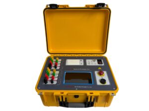
Click the image to know more about Transformer DC Resistance Tester.
What Is Winding and Contact Resistance Testing?
Winding and contact resistance testing is a method used to measure the DC resistance of electrical paths inside transformers, circuit breakers, busbars, and other power equipment.
The test helps engineers identify problems such as:
- Loose electrical connections
- Poor welding or crimping points
- Corroded contact surfaces
- Damaged conductor joints
- Transformer winding abnormalities
- Circuit breaker contact wear
In normal conditions, electrical resistance should remain within a stable range. When resistance becomes higher than expected or differs between phases, it may indicate an internal defect that requires further inspection.
For transformer and switchgear manufacturers, resistance testing is also an important quality-control step before equipment is delivered to customers.
How Does a Micro-Ohmmeter Measure Low Resistance?
A micro-ohmmeter works by applying a stable DC current through the tested component and measuring the voltage drop across it.
According to Ohm’s Law:
R = V / I
Where:
- R = resistance value
- V = measured voltage drop
- I = test current
Because the resistance of transformer windings and electrical contacts is often extremely small (milliohm or micro-ohm range), traditional multimeters cannot provide accurate results.
Modern micro-ohmmeters use:
- High-current DC injection
- Precision voltage measurement
- Automatic calculation
- Temperature compensation
- Digital data storage
Wrindu micro-ohmmeters support different output currents, including 10A, 100A, and 200A options, allowing users to test various applications from transformer windings to high-current busbars.
Why Is the 4-Wire Kelvin Connection Important?
The biggest challenge in low-resistance measurement is eliminating measurement errors caused by test cables and contact resistance.
A 4-wire Kelvin connection solves this problem by separating:
- Current injection leads
- Voltage sensing leads
The current cables supply the test current, while the sensing cables measure only the voltage drop of the device under test.
This method removes the resistance influence of:
- Test leads
- Connection clamps
- Contact points
As a result, engineers can obtain more accurate and repeatable resistance values, especially when measuring micro-ohm-level resistance in transformer windings and breaker contacts.
How Do You Perform a Micro-Ohmmeter Test Correctly?
To achieve reliable results, proper preparation and testing procedures are essential.
Step 1: Disconnect and Secure the Equipment
Before testing:
- Disconnect the equipment from the power system.
- Confirm that no voltage is present.
- Discharge any stored electrical energy.
- Follow safety procedures.
Step 2: Prepare the Test Points
Clean the connection areas before attaching test leads.
Dirty or oxidized surfaces can introduce additional resistance and create inaccurate readings.
Step 3: Connect Kelvin Test Leads
Attach the four-wire Kelvin cables correctly:
- Current leads connect to the test object.
- Voltage sensing leads connect inside the current connection points.
Make sure all connections are tight and stable.
Step 4: Select the Proper Test Current
Choose a suitable current based on the application:
- 10A: Small transformer windings and general resistance tests
- 20A–100A: Circuit breaker contacts and lower resistance connections
- 100A–200A: Large busbars and heavy-duty conductors
The test current should normally remain below about 10% of the equipment rated current to avoid unnecessary heating.
Step 5: Wait for Stable Results
Transformer windings have significant inductance, so the resistance value may require time to stabilize.
Do not record the measurement until the current and resistance reading become steady.
Which Test Current Should Be Used for Different Applications?
The correct test current improves measurement accuracy and reduces testing time.
Typical applications include:
| Application | Recommended Current |
|---|---|
| Transformer winding resistance | 10A–20A |
| Circuit breaker contact resistance | 50A–200A |
| Busbar resistance testing | 100A–200A |
| Small electrical connections | 1A–10A |
Higher current provides a stronger measurement signal, especially for extremely low resistance values.
However, excessive current can increase temperature and affect the measurement result, so the current must always match the equipment type.
How Do You Analyze Transformer Winding Resistance Results?
After completing the test, measured values should be compared with:
- Factory test reports
- Transformer nameplate data
- Previous maintenance records
Temperature correction is necessary because conductor resistance changes with temperature.
For three-phase transformers:
- Similar phase resistance values usually indicate normal conditions.
- Large differences between phases may indicate internal problems.
A resistance imbalance of more than 1%–2% may require further investigation, including:
- Tap changer inspection
- Transformer turns ratio testing
- Dissolved gas analysis (DGA)
Long-term resistance records also help engineers identify gradual equipment aging.
What Are the Common Errors During Micro-Ohmmeter Testing?
Even high-accuracy instruments can produce incorrect results if testing procedures are poor.
Common mistakes include:
Poor Contact Preparation
Dirty or oxidized connection points increase contact resistance and create false readings.
Incorrect Lead Connection
Using a two-wire connection instead of a Kelvin connection introduces cable resistance errors.
Insufficient Stabilization Time
Testing transformers before the current stabilizes can result in unstable measurements.
Ignoring Temperature Effects
Resistance values change with temperature. Without correction, test results from different conditions cannot be compared accurately.
Lack of Equipment Calibration
Regular calibration ensures measurement accuracy and maintains compliance with quality standards such as ISO 9001.
How Do You Choose the Right Micro-Ohmmeter?
When selecting a micro-ohmmeter, consider the following factors:
Test Current Range
Choose equipment based on the application:
- Factory transformer testing
- Circuit breaker maintenance
- Substation inspection
- Busbar quality control
Measurement Resolution
For professional applications, a resolution of 0.1μΩ or 1μΩ is commonly required.
Data Recording Capability
Advanced instruments should provide:
- Internal memory
- Automatic reports
- USB communication
- Test history management
Portability and Safety
Field testing requires lightweight equipment with strong protection against industrial environments.
How Can OEM Manufacturers Benefit from Customized Micro-Ohmmeters?
For transformer and electrical equipment manufacturers, customized testing solutions improve production efficiency and quality consistency.
OEM micro-ohmmeters can include:
- Customized software functions
- Automatic testing sequences
- Brand-specific reports
- Multiple language support
- Production-line integration
These features help manufacturers create standardized inspection processes and meet international customer requirements.
How Do Suppliers Improve Micro-Ohmmeter Performance for Global Markets?
Different industries and regions may require different testing functions.
Suppliers can optimize micro-ohmmeters by adding:
- Flexible current ranges
- Digital reporting systems
- Improved safety functions
- International certifications
- Customized accessories
These improvements allow testing equipment to be used in:
- Power utilities
- Renewable energy projects
- Railway systems
- Industrial plants
- Transformer factories
Frequently Asked Questions About Micro-Ohmmeter Testing
What is the minimum resistance a micro-ohmmeter can measure?
Most industrial micro-ohmmeters can measure resistance down to micro-ohm levels. Depending on the test current and instrument design, some models can achieve 0.1μΩ resolution.
Why is DC current used for winding resistance testing?
DC current is used because it measures pure resistance without the influence of inductive reactance and capacitive effects. This provides more accurate winding and contact resistance results.
How often should a micro-ohmmeter be calibrated?
Most manufacturers recommend calibration every 12 months. More frequent calibration may be needed when the instrument is used frequently in harsh environments.
Can a micro-ohmmeter damage transformer windings?
No, when the correct test current and duration are used. Normally, the test current should remain within recommended limits to prevent unnecessary heating.
What causes high contact resistance in circuit breakers?
Common causes include:
- Contact oxidation
- Mechanical wear
- Loose connections
- Poor contact pressure
- Surface contamination
Can micro-ohmmeters be used for factory quality inspection?
Yes. Many manufacturers use micro-ohmmeters for production testing of transformers, switchgear, cables, and high-current components before shipment.
Conclusion
A micro-ohmmeter is an essential tool for detecting low-resistance problems in transformers, circuit breakers, and electrical connections. With proper Kelvin connections, suitable test current selection, and correct data analysis, engineers can identify potential failures before they become serious problems.
For manufacturers, OEM suppliers, and power companies, reliable micro-ohm resistance testing improves product quality, increases equipment reliability, and supports safer electrical operations.
