

Is Your Micro-Ohmmeter Accuracy Specification Really Reliable for Field Testing?
Learn how temperature, thermal EMF, and Kelvin connections affect micro-ohmmeter accuracy. Understand measurement errors and improve transformer and contact resistance testing reliability.
Introduction
Accurate low-resistance measurement is critical for transformers, circuit breakers, busbars, generators, and other high-current electrical equipment. A small resistance error that appears insignificant in testing data can hide serious connection problems, overheating risks, or future equipment failures.
Many manufacturers and engineers select micro-ohmmeters based only on the advertised accuracy value, such as “0.2% accuracy.” However, this number alone does not always represent the real measurement uncertainty in industrial environments.
A micro-ohmmeter’s actual performance depends on many factors, including:
- Measurement range selection
- Calibration traceability
- Temperature conditions
- Thermal electromotive force (EMF)
- Electromagnetic interference
- Test current stability
For power equipment manufacturers, utilities, and maintenance companies, understanding the complete accuracy calculation is essential for producing reliable and legally acceptable test reports.
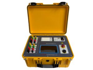
Click the image to know more about Transformer DC Resistance Tester.
What Does Accuracy Class Mean for a Micro-Ohmmeter?
An accuracy class defines the maximum measurement error allowed for a testing instrument under specified conditions. It shows how close the measured value is compared with a recognized reference resistance standard.
For example, a Class 0.2 micro-ohmmeter means the instrument has a maximum specified error under controlled laboratory conditions.
However, accuracy class is not a simple guarantee that every field measurement will always have only 0.2% error.
The actual measurement uncertainty is usually calculated by considering:
- Percentage of measured value error
- Percentage of full-scale range error
- Temperature influence
- External interference
- Instrument stability
The general measurement error formula is:
Total Measurement Error = Reading Error + Range Error + Environmental Influence
For industrial resistance testing, selecting a micro-ohmmeter only according to the accuracy class can create misleading results.
Why Can a 0.2% Accuracy Micro-Ohmmeter Show Larger Errors in the Field?
A laboratory accuracy rating is normally verified under controlled conditions, such as:
- Ambient temperature around 23°C ± 3°C
- Stable power supply
- No electromagnetic interference
- Clean connection points
- Controlled humidity
However, real testing environments are very different.
When engineers test high-voltage equipment in substations or factories, they may face:
- Strong magnetic fields
- Temperature changes
- Outdoor weather conditions
- Large current equipment nearby
- Uneven contact surfaces
These factors can increase actual measurement uncertainty.
For example, a micro-ohmmeter rated at Class 0.2 may not achieve the same accuracy when:
- The selected measurement range is incorrect
- The tested resistance is extremely small
- Temperature compensation is not applied
- Thermal EMF is not eliminated
Therefore, engineers should evaluate the complete error specification instead of only checking the headline accuracy value.
How Does Calibration Traceability Improve Micro-Ohmmeter Accuracy?
Calibration traceability creates a documented connection between a testing instrument and internationally recognized measurement standards.
It proves that a micro-ohmmeter’s measurement results can be compared with accurate reference values from national measurement laboratories.
A complete calibration chain usually includes:
Primary Measurement Standard
Primary standards provide the highest level of resistance accuracy.
Examples include:
- Quantum Hall resistance standards
- National resistance references
Typical uncertainty:
Less than ±0.0001%
Secondary Laboratory Standards
High-precision resistance standards are used to calibrate professional measurement equipment.
Typical uncertainty:
Around ±0.001% to ±0.005%
Working Calibration Standards
Industrial calibration devices are used for routine instrument verification.
Typical uncertainty:
Around ±0.01% to ±0.05%
Field Micro-Ohmmeters
Industrial micro-ohmmeters used for transformer and switchgear testing normally achieve:
Around ±0.1% to ±0.5% accuracy depending on model and conditions.
Why Is Calibration Certification Important for Industrial Resistance Testing?
Without a traceable calibration certificate, an accuracy specification has limited value in professional applications.
For industries such as:
- Transformer manufacturing
- Power grid maintenance
- Circuit breaker testing
- Renewable energy projects
measurement results must be supported by reliable documentation.
For example, if a factory measures a busbar connection resistance of 45.2 μΩ, a customer using another calibrated instrument should obtain a similar result within the acceptable tolerance range.
Traceable calibration ensures that:
- Test reports are legally acceptable
- Customer inspections pass smoothly
- Quality records remain reliable
- Different testing locations can compare results accurately
For global electrical equipment suppliers, calibration traceability is an important part of quality management.
Why Is a 0.2% Accuracy Rating Not Enough for Micro-Ohm Measurement?
A single accuracy value does not describe the complete performance of a micro-ohmmeter.
The reason is that accuracy specifications usually focus on the reading error only, while ignoring other factors such as:
- Full-scale range error
- Resolution limitations
- Thermal voltage effects
- Environmental temperature changes
The actual maximum permissible error is normally calculated as:
Measurement Error = ±(Percentage of Reading + Percentage of Full Scale Range)
This means an instrument may appear highly accurate when measuring larger resistance values but produce much higher uncertainty when measuring extremely small resistances.
What Happens When the Measurement Range Is Not Selected Correctly?
The selected measurement range has a major influence on accuracy.
For example:
A technician measures a circuit breaker contact with an expected resistance of 10 μΩ.
The instrument is set to a 20 mΩ range and has:
- Reading accuracy: 0.2%
- Range error: 0.05%
The reading error is very small:
0.2% × 10 μΩ = 0.02 μΩ
However, the range error becomes:
0.05% × 20 mΩ = 10 μΩ
The total possible error becomes approximately:
±10.02 μΩ
This error is larger than the actual resistance being measured.
The result shows why engineers should always select the lowest suitable measurement range instead of relying only on the instrument accuracy label.
