

Ground Resistance Testing: The Complete Guide to Earth Resistance Measurement and Safety
Learn what ground resistance testing is, how the 3-point fall-of-potential method works, testing procedures, applications, common errors, and how to improve grounding system safety.
What Is Ground Resistance Testing and Why Is It Important?
Ground resistance testing is an essential electrical measurement method used to evaluate the performance and safety of grounding systems.
A grounding system provides a low-resistance path for fault current, lightning current, and leakage current to flow safely into the earth. If the grounding resistance is too high, fault current may not be discharged effectively, which can result in:
- Equipment damage
- Electrical hazards
- Unexpected system failures
- Safety risks for operators
By measuring grounding resistance regularly, engineers can confirm whether grounding systems operate correctly and comply with electrical safety requirements.
Ground resistance testing is widely used in:
- Power substations
- Transformer grounding systems
- Industrial plants
- Renewable energy facilities
- Telecommunication towers
- Electrical installations
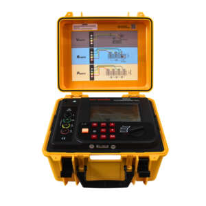
Click the picture to know more about Wrindu Earth Resistance Tester.
How Does a Ground Resistance Test Work?
A ground resistance test measures the resistance between a grounding electrode and the surrounding earth.
The basic principle follows Ohm’s Law:
R = V / I
Where:
- R = Ground resistance
- V = Measured voltage drop
- I = Test current applied
A ground resistance tester injects a controlled test current into the earth and measures the resulting voltage difference.
The instrument then calculates the grounding resistance value automatically.
What Is the 3-Point Ground Resistance Test Method?
The 3-point ground resistance test, also known as the fall-of-potential method, is one of the most commonly used methods for measuring grounding resistance.
This method uses three electrodes:
1. Test Electrode (X)
The test electrode is the grounding system being evaluated.
Examples:
- Transformer grounding grid
- Substation earth electrode
- Equipment grounding conductor
2. Current Electrode (C)
The current electrode creates a current path through the soil.
A known current flows between the test electrode and current electrode.
3. Potential Electrode (P)
The potential electrode measures the voltage drop between itself and the test electrode.
The tester uses this voltage measurement to calculate grounding resistance.
How Does the 3-Point Fall-of-Potential Method Calculate Resistance?
During testing:
- The instrument sends AC test current between X and C.
- The voltage between X and P is measured.
- The resistance value is calculated using:
Ground Resistance = Voltage / Current
The measurement result represents the resistance of the complete grounding system.
This method is widely accepted because it directly evaluates the relationship between current flow and voltage drop in the earth.
How Do You Perform a 3-Point Ground Resistance Test Step by Step?
Step 1: Prepare the Grounding System
Before testing:
- Identify the grounding electrode
- Disconnect parallel grounding paths if required
- Check test equipment condition
This prevents other grounding connections from affecting measurement accuracy.
Step 2: Place Auxiliary Electrodes
Install:
- Current electrode (C)
- Potential electrode (P)
in the soil around the grounding electrode.
A common arrangement places:
- Potential electrode at approximately 62% of the distance between X and C
- Current electrode far enough away to avoid overlapping resistance zones
Step 3: Apply Test Current
The ground resistance tester applies a controlled AC current through the earth.
AC testing is preferred because it reduces polarization effects caused by direct current.
Step 4: Measure Voltage Drop
The tester measures the voltage difference between:
- Test electrode (X)
- Potential electrode (P)
Step 5: Calculate Ground Resistance
The instrument automatically calculates the final resistance value.
Engineers can then compare the result with required safety limits.
What Is the Recommended Electrode Distance for Ground Resistance Testing?
Electrode spacing is one of the most important factors affecting measurement accuracy.
For a typical grounding electrode:
| Electrode | Recommended Position |
|---|---|
| Test Electrode (X) | Grounding system under test |
| Potential Electrode (P) | Around 62% distance from X to C |
| Current Electrode (C) | Located far enough away to establish a stable earth reference |
For example:
A grounding electrode with approximately 2 m depth may require:
- Potential electrode: about 15 m away
- Current electrode: about 25 m away
However, actual distances depend on:
- Soil resistivity
- Grounding system size
- Electrode depth
- Site conditions
What Are the Different Methods for Ground Resistance Testing?
Different applications require different measurement methods.
3-Point Fall-of-Potential Method
The most common method for accurate grounding resistance measurement.
Advantages:
- High accuracy
- Suitable for substations and industrial systems
- Widely accepted internationally
4-Point Soil Resistivity Testing
The 4-point method is mainly used to measure soil resistivity.
It helps engineers design:
- Ground grids
- Lightning protection systems
- Substation grounding networks
Clamp-On Ground Resistance Testing
This method allows measurement without disconnecting the grounding conductor.
Advantages:
- Fast testing
- Convenient maintenance
- Suitable for multiple grounding paths
What Factors Affect Ground Resistance Test Results?
Several environmental and installation factors can influence measurement accuracy.
Soil Resistivity
Soil conductivity changes depending on:
- Moisture content
- Temperature
- Soil composition
Generally:
Wet soil → Lower resistance
Dry soil → Higher resistance
Electrode Condition
Corrosion, loose connections, or damaged electrodes may increase grounding resistance.
Electrode Spacing
Incorrect spacing may cause resistance area overlap and inaccurate readings.
Electrical Interference
Nearby equipment such as:
- transformers
- transmission lines
- generators
may introduce measurement errors.
Why Is Ground Resistance Testing Important for Electrical Safety?
A reliable grounding system protects both people and equipment.
Accurate testing helps:
Protect Electrical Equipment
Proper grounding reduces damage caused by:
- short circuits
- lightning strikes
- leakage currents
Improve Personnel Safety
Low grounding resistance reduces dangerous touch voltage and step voltage.
Maintain System Reliability
Regular testing helps identify:
- aging grounding systems
- corrosion problems
- connection failures
Where Is Ground Resistance Testing Used?
Power Utilities and Substations
Ground resistance testing verifies transformer and substation grounding performance.
Applications include:
- transformer neutral grounding
- switchgear grounding
- grounding grid inspection
Industrial Facilities
Factories use grounding tests to protect:
- motors
- production equipment
- control systems
Renewable Energy Systems
Solar farms and wind power plants require grounding verification for:
- lightning protection
- inverter systems
- electrical safety
OEM Manufacturers
Electrical equipment manufacturers use grounding tests for:
- quality control
- product certification
- factory inspection
When Should Ground Resistance Testing Be Performed?
Recommended testing situations include:
During New Installation
Verify grounding system performance before energization.
During Preventive Maintenance
Regular testing identifies degradation before failures occur.
After Repairs
Confirm grounding performance after system modifications.
After Lightning Events
Check whether grounding systems remain effective.
What Are Common Problems During Ground Resistance Testing?
Problem 1: Incorrect Electrode Placement
Incorrect spacing may create inaccurate readings.
Solution:
Follow recommended electrode distances and perform stability checks.
Problem 2: High Soil Resistance
Dry or rocky soil may increase grounding resistance.
Solution:
Improve grounding design or install additional grounding electrodes.
Problem 3: Electrical Noise Interference
Nearby electrical equipment may affect measurement.
Solution:
Use advanced testers with interference rejection technology.
How to Choose the Right Ground Resistance Tester?
When selecting a ground resistance tester, consider:
Measurement Accuracy
High-quality instruments provide stable and repeatable results.
Testing Methods
A professional tester should support:
- 3-point testing
- 4-point soil resistivity testing
- resistance measurement
Field Application
Portable design is important for:
- substations
- outdoor projects
- maintenance teams
Safety Features
Look for:
- overvoltage protection
- reliable insulation design
- international certifications
How Does Wrindu Support Reliable Ground Resistance Testing?
Wrindu develops professional electrical testing equipment for power utilities, industrial companies, and OEM manufacturers.
Wrindu testing solutions are designed to provide:
- Accurate grounding resistance measurement
- Reliable field performance
- Easy operation
- Stable test results
- Compliance with international quality requirements
With advanced manufacturing capability and ISO9001 quality management, Wrindu supports engineers worldwide in improving electrical safety and grounding reliability.
FAQs
What is a ground resistance test?
A ground resistance test measures the resistance between a grounding electrode and the earth to verify grounding system performance and electrical safety.
What is the 3-point ground resistance test?
The 3-point test uses a test electrode, current electrode, and potential electrode to measure grounding resistance using the fall-of-potential method.
How does the fall-of-potential method work?
The tester applies current through the earth and measures voltage drop to calculate resistance using Ohm’s Law.
What distance should be used between ground test electrodes?
The potential electrode is commonly placed at approximately 62% of the distance between the test electrode and current electrode.
How often should ground resistance testing be performed?
Testing frequency depends on regulations and applications. Many facilities perform tests annually or during scheduled maintenance.
Can ground resistance testing be used for substations?
Yes. It is widely used for transformer substations, transmission systems, and high-voltage electrical installations.
What causes high grounding resistance?
Common causes include:
- Dry soil
- Corroded electrodes
- Poor connections
- Insufficient grounding design
What instrument is used for ground resistance testing?
A ground resistance tester, also called an earth resistance tester, is used to measure grounding system resistance.
Conclusion
Ground resistance testing is a key method for ensuring electrical safety, equipment protection, and reliable operation.
The 3-point fall-of-potential method provides accurate and widely accepted grounding resistance measurements for substations, industrial facilities, and electrical installations.
By using professional testing equipment and performing regular inspections, engineers can detect grounding problems early, reduce electrical risks, and maintain system reliability.
