

How to Test a Current Transformer: A Step-by-Step Guide to Ratio, Polarity, Excitation, and Burden Tests
Learn how to test a current transformer step by step. This guide covers CT ratio, polarity, excitation, knee point, resistance, burden, and error tests.
A current transformer (CT) turns a large primary current into a small secondary current. Meters and protection relays then work with that small signal. When the signal is wrong, protection may trip at the wrong time. It may also fail to trip when it should. That is why CT testing matters.
This guide walks you through the eight tests that engineers run most often. You will learn what each test checks, how to run it, and how to read the result.
If you want the wider picture first, start with our guide to CT and PT analyzers. It explains how the same instrument tests both current and voltage transformers.
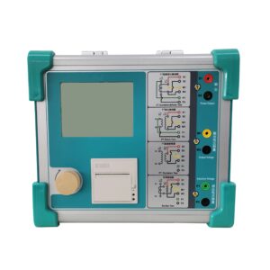
Click the image to know more about Wrindu CT and PT Analyzer.
What Does a Current Transformer Do?
A CT works like a step-up transformer for current. The primary winding carries the full line current. The secondary winding delivers a much smaller current, usually 1 A or 5 A.
For example, a 1000/5 A CT takes 1000 A on the primary side. It sends 5 A to the secondary side.
Two jobs depend on that secondary current:
- Measurement — meters and energy counters read the current to bill customers or to show load.
- Protection — relays watch the current. They trip a breaker when a fault current appears.
Both jobs need an accurate and reliable signal. A CT with a wrong ratio or wrong polarity sends a misleading signal, and the equipment behind it makes a wrong decision.
Why Should You Test a CT?
You test a CT to answer three simple questions:
- Does the CT match its nameplate? Ratio and polarity must match the design data.
- Is the CT healthy? Winding resistance and excitation behavior show core and winding condition.
- Will it perform under fault current? Knee point and burden tests show whether the CT still works when current rises high.
Engineers test CTs at four moments in the life of a substation:
- Commissioning — before the CT enters service.
- Routine maintenance — on a scheduled cycle.
- Troubleshooting — after a protection misoperation.
- Quality inspection — at the factory, before delivery.
What Do You Need Before You Start?
Field CT testing is safe only when you prepare well. Run through this checklist first:
- De-energize the primary circuit and follow your lockout/tagout rule.
- Isolate the CT secondary circuit. Never open a loaded CT secondary.
- Short and ground the secondary terminals before you disconnect them.
- Discharge and ground any nearby capacitor or surge equipment.
- Wear the correct PPE for the voltage class.
- Record the nameplate data: ratio, accuracy class, rated burden, rated knee point, and serial number.
- Note the ambient temperature. Resistance results shift with temperature.
Once the CT sits in a safe state, connect your test leads and start the tests.
The Eight Core CT Tests at a Glance
| Test | What It Checks | Typical Range | |
| 1 | Ratio test | Actual ratio against the nameplate ratio | 1–10000 |
| 2 | Polarity test | Terminal polarity relationship (P1/P2 vs S1/S2) | — |
| 3 | Excitation test | Core behavior as secondary voltage rises | Up to knee point |
| 4 | Knee point test | Point where the core enters strong saturation | Up to 30 kV |
| 5 | Secondary winding resistance | Health of the secondary winding and its leads | 0–300 Ω |
| 6 | Burden test | Real load on the secondary circuit | 0–300 VA |
| 7 | Ratio error | Measurement accuracy in percentage terms | ±0.2% |
| 8 | Phase displacement | Phase shift between primary and secondary current | ±3 min |
A modern CT analyzer runs all eight tests from one instrument. That saves time in the field and keeps every result in one report.
1. CT Ratio Test
What it checks: The actual transformation ratio.
How to run it: The analyzer injects a test current into the primary or secondary side. It measures the current on the other side and calculates the ratio.
How to read the result: Compare the measured ratio with the nameplate ratio. For a 1000/5 A CT, the correct ratio is 200:1. A small deviation is normal. A large deviation points to a connection problem, a shorted turn, or wrong nameplate data.
Red flags: A ratio that drifts by more than the accuracy class allows. A ratio that differs between phases on the same circuit.
2. CT Polarity Test
What it checks: The polarity relationship between primary terminals (P1, P2) and secondary terminals (S1, S2).
How to run it: The analyzer applies a small signal and reads the direction of the induced secondary current. It then reports whether the CT is in subtractive or additive polarity.
How to read the result: A protection-grade CT should normally show subtractive polarity. P1 and S1 sit at the same instantaneous direction.
Red flags: Reversed polarity. This flips the current direction that the relay sees. Differential and directional protection then misoperate. A miswired CT caused many real-world protection failures, so always check polarity at commissioning.
3. CT Excitation Test
What it checks: How the core responds as secondary voltage increases.
How to run it: Keep the primary winding open. Apply an increasing AC voltage to the secondary winding. Record the excitation current at each step.
How to read the result: The instrument plots an excitation curve of voltage against current. A healthy core follows a smooth curve. A curve that rises too early suggests a core problem such as shorted turns.
Red flags: An excitation current that runs much higher than the reference curve. A curve that bends far below the expected knee point.
Engineers care about this test most on protection-class CTs. Core saturation changes the current signal that reaches the relay, and the relay may then fail to operate correctly.
4. CT Knee Point Test
What it checks: The knee point voltage and current on the excitation curve.
What is a knee point? The knee point is the spot on the excitation curve where a further 10% rise in voltage causes a 50% rise in excitation current. Below the knee point, the CT behaves well. Above it, the core enters strong saturation and the secondary current no longer follows the primary current.
How to run it: The analyzer raises the secondary voltage and watches the curve. It then marks the knee point automatically.
How to read the result: Compare the knee point voltage with the specified value on the nameplate or in the protection study.
Red flags: A knee point voltage far below the specified value. This means the CT saturates early and may not drive the relay during a fault.
The RDHG-E Variable Frequency Transformer Comprehensive Tester performs CT knee point testing up to 30 kV.
5. CT Secondary Winding Resistance Test
What it checks: The DC resistance of the secondary winding and its internal leads.
How to run it: Inject a small DC current into the secondary winding and measure the voltage drop. The analyzer calculates resistance directly.
How to read the result: Compare the measured value with the nameplate value. Also compare phase by phase. The three phases should read close to each other.
Red flags: A resistance that runs much higher than the nameplate value. This points to a loose terminal, a corroded joint, or a damaged winding. Remember that resistance rises with temperature, so correct the value to a reference temperature before you compare.
6. CT Burden Test
What it checks: The real load that the secondary circuit places on the CT.
What is burden? Burden is the total load on the secondary circuit. Relays, meters, terminal blocks, and cable resistance all add to it. Engineers express burden in volt-amperes (VA) at a stated power factor.
How to run it: Connect the analyzer across the secondary circuit and measure the actual burden.
How to read the result: Compare the measured burden with the rated burden of the CT. The load should stay inside the rated value with some margin.
Red flags: A burden above the rated value. An overloaded CT loses accuracy and saturates earlier. Adding a new meter or relay to an old circuit often pushes the burden over the limit.
7. CT Ratio Error Test
What it checks: How closely the CT follows its specified ratio, expressed as a percentage.
How to run it: The analyzer compares the primary current with the secondary current multiplied by the rated ratio. It reports the difference as a percentage.
How to read the result: The allowed error depends on the accuracy class. A 0.2 class CT must stay inside ±0.2%. A 5P protection CT has its own error limits.
Red flags: An error that grows as current rises. This often signals a core problem or a burden problem.
8. CT Phase Displacement Test
What it checks: The phase angle between the primary current and the secondary current.
How to run it: The analyzer measures both current phasors and reports the angle difference in minutes.
How to read the result: Protection relays and revenue meters depend on phase accuracy. A small shift is normal. A large shift distorts power measurement and directional protection.
The RDHG-E measures phase with an accuracy of ±3 minutes and a resolution of 0.3 minutes.
How Do You Read CT Test Results?
Never judge a CT from one number alone. Follow this order:
- Check the trend. Compare phases with each other, and compare this test with the last one.
- Check the conditions. Test frequency, temperature, and lead length all change the reading.
- Check the source. Confirm the nameplate data before you compare anything with it.
- Check the standard. Compare the result with the accuracy class and the protection study, not with a general rule of thumb.
A clean set of results across all eight tests gives you confidence. One odd number usually means you should repeat the test and inspect the wiring.
What Mistakes Do Engineers Make During CT Testing?
- They forget the primary circuit. An open primary or a live adjacent circuit ruins the test and risks injury.
- They test with the secondary burden still connected. This skews ratio and excitation results.
- They ignore temperature. Winding resistance looks wrong when you skip temperature correction.
- They trust the nameplate without checking it. Nameplate data goes missing or gets copied wrong after a rebuild.
- They use the wrong test frequency. A low test frequency needs the correct compensation, or the knee point shifts.
- They test only the ratio. Ratio alone cannot show core saturation. You need the excitation and knee point tests too.
What Equipment Do You Need for CT Testing?
A traditional setup needs several instruments: a voltage regulator, a voltage booster, a current booster, a voltmeter, an ammeter, and a phase meter. You also need to wire them together and calculate results by hand.
A multifunctional CT analyzer replaces that whole setup. It applies the test signal, measures the values, calculates the parameters, and prints the report.
The Wrindu RDHG-E Variable Frequency Transformer Comprehensive Tester combines CT and PT testing in one unit. Key specifications:
- CT and PT ratio range: 1–10000, accuracy ±0.2%
- Voltage accuracy: ±0.1%
- Resistance range: 0–300 Ω
- AC burden range: 0–300 VA
- Knee point test: up to 30 kV
- Phase accuracy: ±3 minutes, resolution 0.3 minutes
- Output: 0–180 Vrms, 12 Arms, 36 A peak
- Data storage: 1000 groups, with USB transfer and a built-in printer
- Power supply: AC 220 V ±10%, 50 Hz
- Working temperature: −10°C to 50°C
It also uses a variable-frequency, low-frequency test method. That method cuts the weight and the wiring of the test kit and makes one-person field testing practical.
Frequently Asked Questions
How do I test a current transformer in the field? Isolate the CT, short the secondary, and record the nameplate data. Then connect a CT analyzer and run the ratio, polarity, excitation, knee point, resistance, and burden tests. The analyzer calculates the results and stores them.
What is a good CT ratio? There is no single good ratio. The correct ratio depends on the primary current, the secondary circuit, and the transformer design. Always compare the measured ratio with the specified ratio for that CT.
What is the difference between an excitation test and a ratio test? A ratio test checks the transformation ratio at a low test signal. An excitation test checks how the core behaves as the secondary voltage rises. Ratio testing confirms the design. Excitation testing confirms the core condition.
How often should I test a CT? Most utilities test CTs at commissioning and then on a routine maintenance cycle. You should also test a CT after a protection misoperation, after a rebuild, or when the load pattern changes.
Can I test a CT while it stays in service? No. CT testing needs an isolated and de-energized circuit. Testing a live CT secondary is dangerous and can damage equipment.
What is knee point voltage? Knee point voltage is the secondary voltage where the core starts to saturate strongly. At that point, a 10% voltage rise causes a 50% current rise.
Can one instrument handle both CT and PT testing? Yes. A combined CT and PT analyzer handles both. Our pillar guide on CT and PT analyzers explains the shared functions in detail.
