

4-Point Soil Resistivity Testing vs 3-Point Ground Resistance Testing: What Is the Difference?
Learn the difference between 4-point soil resistivity testing and 3-point ground resistance testing, including principles, applications, procedures, and how to choose the right method.
Why Are Soil Resistivity Testing and Ground Resistance Testing Important?
A reliable grounding system is essential for electrical safety, equipment protection, and stable operation of power systems.
Before designing or maintaining a grounding system, engineers need to understand two important electrical parameters:
- Soil resistivity
- Ground resistance
Although these two terms are often used together, they describe different electrical characteristics.
Soil resistivity testing evaluates the natural ability of soil to resist electrical current flow, while ground resistance testing measures the performance of an installed grounding system.
Understanding the difference between these two tests helps engineers select the correct measurement method for grounding design, installation verification, and preventive maintenance.
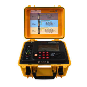
Click the picture to know more about Wrindu Earth Resistance Tester.
What Is Soil Resistivity Testing?
Soil resistivity testing is a measurement method used to determine how easily electrical current can flow through the soil.
The measurement result is expressed in:
Ohm-meter (Ω·m)
Soil resistivity depends on several factors, including:
- Soil composition
- Moisture content
- Temperature
- Chemical properties
- Soil layers
A lower soil resistivity value means the soil allows current to flow more easily.
A higher soil resistivity value indicates that the soil provides greater resistance to electrical current.
Why Is Soil Resistivity Measurement Important for Grounding Design?
Soil resistivity testing is mainly performed before installing a new grounding system.
Engineers use soil resistivity data to design grounding systems that can achieve the required safety performance.
How Does Soil Resistivity Help Engineers Design Grounding Systems?
Accurate soil resistivity information helps determine:
- Number of grounding electrodes required
- Ground rod installation depth
- Ground grid structure
- Expected grounding resistance
- Lightning protection design
Without accurate soil information, a grounding system may be incorrectly designed and fail to provide adequate protection.
What Is the 4-Point Soil Resistivity Test Method?
The 4-point soil resistivity test is also known as the Wenner method.
This method uses four electrodes placed in a straight line with equal spacing.
The four electrodes include:
- Two current electrodes
- Two potential electrodes
The method is widely used for analyzing soil characteristics before grounding system construction.
How Does the Wenner Method Work?
During a 4-point soil resistivity test:
- The tester sends electrical current into the soil through the two outer electrodes.
- The two inner electrodes measure the voltage difference.
- The instrument calculates soil resistivity based on the measured values and electrode spacing.
The basic formula is:
ρ = 2πaR
Where:
- ρ = Soil resistivity
- a = Distance between electrodes
- R = Measured resistance
The result represents the resistance characteristics of the soil at a specific depth.
How Does Electrode Spacing Affect Soil Resistivity Results?
Electrode spacing determines the approximate depth of soil being evaluated.
What Happens When Electrode Spacing Is Increased?
A larger electrode distance allows current to travel deeper into the soil.
This helps engineers analyze deeper soil layers.
What Happens When Electrode Spacing Is Reduced?
A smaller distance mainly evaluates shallow soil conditions.
By performing multiple measurements with different spacing distances, engineers can build a clearer understanding of underground soil characteristics.
What Is Ground Resistance Testing?
Ground resistance testing measures the resistance of an existing grounding system connected to the earth.
Unlike soil resistivity testing, which focuses on soil properties, ground resistance testing evaluates the actual performance of installed grounding equipment.
The measurement unit is:
Ohm (Ω)
A ground resistance test determines whether the grounding system can safely discharge fault current and maintain electrical protection.
How Does the 3-Point Ground Resistance Test Work?
The 3-point ground resistance test, also called the fall-of-potential method, is one of the most commonly used grounding measurement methods.
It uses three electrodes:
- Test electrode
- Current electrode
- Potential electrode
What Happens During a 3-Point Ground Resistance Test?
The testing process includes:
- A controlled current is injected into the earth between the test electrode and current electrode.
- The voltage drop between the test electrode and potential electrode is measured.
- The ground resistance value is calculated using Ohm’s Law.
Formula:
R = V / I
Where:
- R = Ground resistance
- V = Voltage drop
- I = Test current
What Is the Main Difference Between 4-Point and 3-Point Testing?
The biggest difference is the purpose of measurement.
What Does the 4-Point Method Measure?
The 4-point method measures:
- Soil electrical characteristics
- Soil conductivity
- Resistivity distribution
It is mainly used before grounding system construction.
What Does the 3-Point Method Measure?
The 3-point method measures:
- Installed grounding resistance
- Ground electrode performance
- Grounding system effectiveness
It is mainly used after grounding installation or during maintenance.
What Are the Differences Between Soil Resistivity and Ground Resistance Testing?
| Comparison | 4-Point Soil Resistivity Testing | 3-Point Ground Resistance Testing |
|---|---|---|
| Main Purpose | Analyze soil characteristics | Verify grounding system performance |
| Measurement Unit | Ω·m | Ω |
| Testing Stage | Before installation | After installation |
| Main Method | Wenner method | Fall-of-potential method |
| Main Application | Grounding design | Grounding inspection |
When Should Engineers Perform 4-Point Soil Resistivity Testing?
During New Substation Construction
Large substations require proper grounding design to safely handle fault current.
Soil resistivity testing helps engineers determine:
- Ground grid layout
- Ground conductor arrangement
- Required grounding depth
During Renewable Energy Projects
Solar farms and wind power facilities require effective grounding systems.
Soil resistivity testing supports:
- Lightning protection design
- Equipment grounding planning
- Safety evaluation
During Industrial Facility Planning
Factories and industrial plants use soil analysis before installing electrical systems.
Testing helps avoid grounding problems after construction.
When Should Engineers Perform 3-Point Ground Resistance Testing?
After Grounding System Installation
The 3-point test verifies whether the completed grounding system meets expected performance requirements.
During Preventive Maintenance
Regular testing helps identify:
- Aging grounding systems
- Corroded electrodes
- Loose connections
After Electrical System Modification
Changes to electrical infrastructure may affect grounding performance.
Testing confirms whether the grounding system remains reliable.
What Factors Affect Soil Resistivity and Ground Resistance Measurements?
How Does Soil Moisture Affect Testing Results?
Water content has a major influence on electrical conductivity.
Generally:
- Wet soil → Lower resistance
- Dry soil → Higher resistance
Seasonal changes may cause measurement differences.
How Does Soil Composition Affect Grounding Performance?
Different soil types have different electrical characteristics.
Examples:
- Clay soil usually has better conductivity.
- Sandy soil often has higher resistance.
- Rocky soil may create difficult grounding conditions.
How Does Temperature Affect Measurements?
Extreme temperatures can change soil conductivity.
Frozen soil, for example, may significantly increase resistance values.
What Are Common Mistakes During Soil Resistivity Testing?
Using Incorrect Electrode Spacing
Incorrect spacing can produce inaccurate soil analysis.
Proper electrode distances should be selected based on the required testing depth.
Ignoring Different Soil Layers
Soil resistivity may change significantly underground.
Multiple spacing measurements provide better information for grounding design.
Performing Tests Near Electrical Interference Sources
Nearby electrical equipment may affect results.
Avoid testing close to:
- Power cables
- Transformers
- High-voltage equipment
What Are Common Mistakes During Ground Resistance Testing?
Incorrect Auxiliary Electrode Placement
Poor electrode positioning may cause inaccurate resistance readings.
The fall-of-potential method requires proper spacing between electrodes.
Testing Without Considering Grounding System Structure
Different grounding designs may require different testing approaches.
Engineers should understand the grounding system before measurement.
Ignoring Historical Test Data
A single test result does not always show long-term grounding performance.
Comparing historical measurements helps identify system degradation.
Can Soil Resistivity Testing and Ground Resistance Testing Be Used Together?
Yes.
In large electrical projects, both methods are often used as part of a complete grounding evaluation process.
Step 1: Perform Soil Resistivity Testing
Engineers analyze soil conditions using the 4-point method.
Step 2: Design the Grounding System
Based on soil data, engineers determine:
- Ground grid structure
- Electrode arrangement
- Grounding conductor requirements
Step 3: Install the Grounding System
Step 4: Perform Ground Resistance Testing
The 3-point method verifies whether the installed system performs as designed.
Using both methods provides a complete approach from grounding design to system verification.
How Does Wrindu Support Soil Resistivity and Ground Resistance Testing?
Wrindu provides professional electrical testing solutions for power utilities, industrial companies, and engineering organizations.
Wrindu grounding test equipment helps users achieve:
- Accurate measurement results
- Reliable field performance
- Efficient testing procedures
- Improved grounding system evaluation
From initial grounding design to routine maintenance, accurate measurement helps engineers improve electrical safety and system reliability.
Frequently Asked Questions About Soil Resistivity and Ground Resistance Testing
What Is the Difference Between Soil Resistivity and Ground Resistance?
Soil resistivity describes the electrical characteristics of soil, while ground resistance measures the resistance of an installed grounding system.
Why Is Soil Resistivity Testing Needed Before Grounding Design?
It helps engineers understand soil conditions and design a grounding system that meets safety requirements.
What Is the 4-Point Wenner Method?
The Wenner method is a soil resistivity measurement technique using four equally spaced electrodes to calculate soil resistance characteristics.
Can a Ground Resistance Tester Measure Soil Resistivity?
Some advanced instruments support both ground resistance testing and soil resistivity measurement, depending on the model and configuration.
Which Test Should Be Performed First?
For new grounding projects, soil resistivity testing is usually performed first, followed by ground resistance testing after installation.
Can Soil Conditions Change Ground Resistance Results?
Yes. Changes in moisture, temperature, and soil composition can affect grounding resistance measurements.
Is the 3-Point Method Suitable for Substation Testing?
Yes. The 3-point fall-of-potential method is widely used for substations, transformers, and industrial grounding systems.
Why Are Both Tests Important for Electrical Safety?
Soil resistivity testing helps create a proper grounding design, while ground resistance testing confirms that the installed system works correctly.
Conclusion
4-point soil resistivity testing and 3-point ground resistance testing are two different but complementary methods used in grounding engineering.
The 4-point method helps engineers understand soil conditions and design effective grounding systems.
The 3-point method verifies the actual performance of installed grounding systems.
For substations, industrial facilities, renewable energy projects, and electrical infrastructure, combining both testing methods provides a reliable approach to improving electrical safety and long-term system performance.
