

Vehicle-Mounted Cable Fault Testing System: Working Principles, Components, and Applications
Learn how a vehicle-mounted cable fault testing system works, its main components, cable fault location methods, applications, and key selection tips.
Underground cable faults can interrupt power distribution, industrial production, and railway operations. Finding the exact fault location is difficult because cables are buried underground and often run beneath roads or buildings.
A vehicle-mounted cable fault testing system combines several testing instruments in one vehicle. It helps engineers measure cable length, locate faults, detect underground cable routes, and identify damaged sections.
The WRINDU RDCD-C Vehicle-Mounted Cable Fault Testing System combines cable fault pre-location, high-voltage testing, acoustic-magnetic pinpointing, and cable path detection. This guide explains its working principles, main components, technical specifications, and applications.
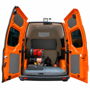
Click the image to know more about Wrindu RDCD-C Vehicle-Mounted Cable Fault Testing System.
What Is a Vehicle-Mounted Cable Fault Testing System?
A vehicle-mounted cable fault testing system is a group of cable testing instruments installed in a vehicle. It is used to detect and locate faults in underground power cables.
Unlike a single cable fault locator, this system combines several testing functions:
- Cable length measurement
- Low-voltage pulse testing
- High-voltage surge testing
- Multiple pulse testing
- Acoustic-magnetic fault pinpointing
- Cable route detection
- Cable identification
These functions help engineers complete different testing steps at the same location.
The WRINDU RDCD-C integrates the testing equipment into one system. The vehicle is not included, so customers can select a suitable vehicle for local installation.
How Does a Vehicle-Mounted Cable Fault Testing System Work?
Cable fault location usually involves two main tasks: estimating the fault distance and finding the exact fault position on the ground.
The RDCD-C uses different instruments for each testing stage.
| Testing Stage | Equipment | Function |
|---|---|---|
| Cable length measurement | RA40 | Measures cable length and calibrates wave velocity |
| Fault pre-location | RA40 | Estimates the fault distance |
| High-voltage testing | High-voltage unit | Tests high-resistance and flashover faults |
| Fault pinpointing | RC11 | Detects acoustic and magnetic signals |
| Cable route detection | R30 | Traces underground cable routes |
| Cable identification | R30 | Identifies the target cable |
Step 1: Measure Cable Length
The operator uses the RA40 to measure cable length and calibrate wave propagation velocity.
These values are needed to calculate the distance between the test point and the fault.
Step 2: Estimate the Fault Distance
The RA40 sends electrical pulses into the cable and analyzes the reflected signals.
The waveform helps identify the fault position along the cable. Low-voltage pulse testing is suitable for many open-circuit and short-circuit faults, while high-resistance faults may require other methods.
Step 3: Apply High-Voltage Testing
High-resistance faults may not produce clear reflections under low-voltage testing.
The system applies a high-voltage impulse to trigger discharge at the damaged insulation point. The resulting signals help the operator estimate the fault distance and prepare for precise pinpointing.
Step 4: Pinpoint the Fault
After pre-location, the operator uses the RC11 to find the fault position on the ground.
The instrument detects sound and magnetic signals produced by electrical discharge. By comparing these signals along the cable route, the operator can narrow down the fault location.
Step 5: Trace the Cable Route
The R30 detects the underground cable route and measures burial depth.
It also helps identify the target cable when several cables run close together. This reduces the risk of excavating the wrong cable.
What Are the Main Cable Fault Location Methods?
Different faults require different testing methods. The choice depends on fault resistance, cable insulation, and the electrical condition of the cable.
Low-Voltage Pulse Reflection Method (TDR)
Time Domain Reflectometry (TDR) uses low-voltage pulses to estimate cable fault distance.
The instrument sends a pulse into the cable. When the pulse reaches an impedance change, part of the signal reflects back to the test end.
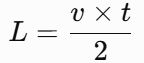
The instrument calculates the distance from the pulse travel time.
[
L=\frac{v\times t}{2}
]
Where:
- (L) = Distance to the reflection point (m)
- (v) = Pulse propagation velocity (m/s)
- (t) = Round-trip travel time (s)
TDR is commonly used for open-circuit, short-circuit, and low-resistance faults. It may not detect some high-resistance insulation faults because they produce weak reflections.
High-Voltage Surge Method
High-voltage surge testing is used to locate faults that cannot be detected clearly with low-voltage pulses.
The system applies a high-voltage impulse to the cable. When the voltage reaches the breakdown level of the damaged insulation, the fault point may discharge.
The discharge produces electrical and acoustic signals. The electrical waveform helps estimate the fault distance, while the acoustic signal supports ground-level pinpointing.
Multiple Pulse Method (ARM)
The Arc Reflection Method (ARM) helps locate certain high-resistance faults.
A high-voltage impulse creates a temporary arc at the fault point. The instrument then uses a low-voltage pulse to obtain a reflection from this temporary low-resistance path.
The operator compares the resulting waveform with a reference waveform to estimate the fault distance.
ARM is useful when a conventional low-voltage pulse cannot produce a clear fault reflection.
High-Voltage Burn-Through Method
Burn-through applies DC voltage and current to a high-resistance fault point.
The current heats the damaged insulation and may create a more stable, lower-resistance path. This makes subsequent fault location easier in some cases.
The RDCD-C supports:
| Parameter | Range |
|---|---|
| Burn-Through Voltage | 0–40 kV |
| Burn-Through Current | 0–100 mA |
Burn-through is not suitable for every cable fault. Operators must check the cable condition before using this method.
Acoustic and Magnetic Fault Pinpointing
A high-voltage discharge produces sound waves and magnetic signals.
The RC11 detects both signals. The magnetic signal helps identify the discharge event, while the acoustic signal helps locate its position above ground.
Operators move along the cable route and compare the signal timing to narrow down the fault location.
Electromagnetic Cable Route Detection
Cable route detection uses electromagnetic signals to trace underground cables.
A transmitter introduces a signal into the cable through direct connection, clamp coupling, or induction. A receiver detects the signal above ground.
The operator follows the signal to identify the cable route and measure burial depth. This method also helps distinguish the target cable from nearby cables.
The RDCD-III/R30 supports 10 active frequencies and 2 passive frequencies.
What Types of Cable Faults Can a Vehicle-Mounted Tester Detect?
The RDCD-C supports different testing methods for common underground cable faults.
| Fault Type | Typical Condition | Testing Method |
|---|---|---|
| Open-Circuit Fault | Conductor is broken | Low-voltage pulse |
| Short-Circuit Fault | Conductors are connected unintentionally | Low-voltage pulse |
| Low-Resistance Fault | Insulation damage creates a low-resistance path | Low-voltage pulse |
| High-Resistance Leakage | Insulation leaks under test voltage | High-voltage testing |
| High-Resistance Flashover | Damaged insulation breaks down under high voltage | Surge and multiple pulse methods |
The test method depends on the fault resistance and cable condition. Some intermittent faults may require repeated testing.
What Are the Main Components of a Vehicle-Mounted Cable Fault Testing System?
The RDCD-C includes several testing instruments. Each one performs a specific task during cable fault location.
RDCD-C/RA40 Operation Console
The RA40 is the main control and measurement unit. It supports cable length measurement, wave velocity calibration, fault pre-location, and waveform analysis.
| Parameter | Specification |
|---|---|
| Test Distance | 5 m–100 km |
| Pinpointing Accuracy | ±0.2 m (product-stated value) |
| Sampling Frequency | 6.25–200 MHz |
| Burn-Through Voltage | 0–40 kV |
| Burn-Through Current | 0–100 mA |
| Display | 15-inch Industrial LCD |
| Operating System | Linux |
The measurement range depends on cable length, signal attenuation, fault type, and test conditions.
The stated ±0.2 m accuracy should be distinguished from the distance error of fault pre-location.
High-Voltage Control System
The high-voltage unit supplies the voltage and impulse energy needed for high-resistance fault testing.
| Parameter | Specification |
|---|---|
| Output Voltage | 0–32 kV |
| Maximum Impulse Energy | 2048 J |
| Built-in Capacitor 1 | 4 μF / 32 kV |
| Built-in Capacitor 2 | 16 μF / 16 kV |
| Built-in Capacitor 3 | 64 μF / 8 kV |
| Impulse Interval | 1–10 s |
| Display | 5-inch Color LCD |
| Discharge | Automatic discharge |
The three capacitors provide different voltage and capacitance configurations. The actual impulse energy depends on the selected settings.
Cable Reel and Safety Monitoring System
The cable reel system connects the testing equipment to the cable under test.
| Component | Length |
|---|---|
| High-Voltage Cable | 50 m |
| Grounding Cable | 50 m |
| Power Cable | 50 m |
| Step Voltage Cable | 15 m |
The system monitors grounding, step voltage, pulse temperature, and safety switch status.
When it detects an abnormal condition, it can issue an alarm and activate high-voltage cutoff and discharge protection.
RDCD-III/RC11 Cable Fault Locator
The RC11 uses acoustic and magnetic signals to pinpoint underground cable faults.
| Parameter | Specification |
|---|---|
| Detection Method | Acoustic and magnetic field detection |
| Sensor Frequency Range | 100–1500 Hz |
| Sound Channel Dynamic Range | More than 104 dB |
| Magnetic Channel Dynamic Range | More than 110 dB |
| Display Resolution | 320 × 240 pixels |
| Signal Processing | Background noise reduction |
| Trigger Adjustment | Automatic adjustment |
The RC11 displays fault direction and relative position. Its ground probes can be used on soft soil, hardened roads, and lawns.
RDCD-III/R30 Cable Path Detector
The R30 traces underground cable routes, measures burial depth, and identifies target cables.
| Parameter | Specification |
|---|---|
| Active Frequencies | 10 |
| Passive Frequencies | 2 |
| Signal Connection | Direct, clamp coupling, induction |
| Detection Functions | Route tracing and depth measurement |
| Cable Identification | Energized and de-energized cables |
| Pre-Calibration | Up to 10 cables |
| Display | Signal strength, direction, depth, and position |
Optional accessories include an A-Frame for locating grounding faults in directly buried cables, a flexible current clamp, and a transmitting clamp.
Where Are Vehicle-Mounted Cable Fault Testing Systems Used?
Vehicle-mounted systems are used by organizations that maintain underground cable networks.
| Industry | Typical Application |
|---|---|
| Power Utilities | Underground power cable fault location |
| Urban Power Networks | Fault detection beneath roads and buildings |
| Railway Systems | Signal and control cable testing |
| Airports | Underground power and control cable inspection |
| Street Lighting | Underground lighting cable fault location |
| Industrial Facilities | Factory power cable maintenance |
| Electrical Contractors | On-site cable testing services |
Power Distribution Networks
Power utilities use underground cables to supply residential, commercial, and industrial areas.
When a cable fails, engineers need to estimate the fault distance and locate the exact position before excavation. The RDCD-C supports both tasks.
Railway and Airport Infrastructure
Railways and airports use underground cables for power, signaling, and control systems.
Cable fault testing equipment helps maintenance teams find damaged sections and trace cable routes before repair work.
Industrial Facilities
Factories and industrial parks often have large underground cable networks.
The RDCD-C supports fault location and cable identification across these networks. The R30 is useful when several cables share the same trench or cable corridor.
What Are the Advantages of a Vehicle-Mounted Cable Fault Testing System?
A vehicle-mounted system combines several instruments in one mobile platform.
Its main functions include:
- Multiple testing methods: Low-voltage pulse, high-voltage surge, multiple pulse, and burn-through testing.
- Fault pre-location: Estimates the distance from the test end to the fault.
- Ground-level pinpointing: Uses acoustic and magnetic signals to find the fault position.
- Cable route detection: Traces underground cables and measures burial depth.
- Cable identification: Helps distinguish the target cable from nearby cables.
- Safety monitoring: Monitors grounding, step voltage, and other operating conditions.
The integrated configuration reduces the need to transport separate instruments for each testing stage.
How Do You Choose the Right Vehicle-Mounted Cable Fault Testing System?
Before buying a vehicle-mounted cable fault testing system, check its testing range, supported methods, cable compatibility, and installation requirements.
| Selection Factor | What to Check |
|---|---|
| Cable Voltage Level | Compatibility with the cables under test |
| Cable Type | XLPE, PVC, paper-insulated, single-core, or three-core cables |
| Fault Types | Open circuit, short circuit, low resistance, and high resistance |
| Pre-Location Methods | TDR, multiple pulse, and high-voltage surge |
| High-Voltage Output | Rated output voltage and impulse energy |
| Pinpointing | Acoustic-magnetic detection |
| Cable Route Detection | Route tracing, depth measurement, and cable identification |
| Safety Protection | Grounding monitoring, interlocks, and discharge |
| Vehicle Installation | Vehicle space, power supply, and mounting requirements |
| Technical Support | Installation guidance, training, and warranty |
Buyers should also confirm whether the vehicle is included. The RDCD-C is supplied without a vehicle, allowing customers to choose a suitable vehicle for local installation.
What Is the Difference Between a Portable Cable Fault Tester and a Vehicle-Mounted System?
A portable cable fault tester usually performs one or several testing functions. A vehicle-mounted system combines multiple instruments for different stages of cable fault location.
| Comparison | Portable Cable Fault Tester | Vehicle-Mounted System |
|---|---|---|
| Configuration | Single instrument or small combination | Integrated testing system |
| Transportation | Carried by operators | Transported by vehicle |
| Fault Pre-Location | Depends on model | Integrated |
| High-Voltage Testing | Depends on model | Integrated |
| Acoustic-Magnetic Pinpointing | May require a separate instrument | RC11 included |
| Cable Route Detection | May require a separate instrument | R30 included |
| Cable Identification | Depends on accessories | Supported by R30 |
| Application | Individual testing tasks | Multiple field testing stages |
Portable equipment is suitable for smaller testing tasks and teams that need to carry instruments manually.
A vehicle-mounted system is more suitable for maintenance teams that perform several testing procedures across large underground cable networks.
What Safety Precautions Are Required for High-Voltage Cable Fault Testing?
High-voltage cable testing involves electrical hazards. Operators must follow the equipment manual and local electrical safety procedures.
1. Isolate the Cable
Disconnect the cable from all power sources. Verify that it is de-energized before connecting the testing equipment.
2. Check Grounding
Inspect all grounding connections before applying high voltage. Use the grounding arrangement specified by the equipment manufacturer.
3. Monitor Step Voltage
Keep personnel away from hazardous ground potential areas during testing. Use the required step-voltage monitoring equipment.
4. Check Safety Interlocks
Test the emergency stop, safety switches, and high-voltage protection functions before operation.
5. Discharge After Testing
Discharge the cable according to the approved procedure. Do not touch the test connections until the cable is confirmed safe and grounded.
6. Use Trained Operators
Only qualified personnel should operate high-voltage testing equipment.
The RDCD-C includes grounding monitoring, step-voltage monitoring, safety switch monitoring, automatic warning, and high-voltage cutoff and discharge functions.
These functions support safe operation but do not replace proper cable isolation and grounding procedures.
Frequently Asked Questions About Vehicle-Mounted Cable Fault Testing Systems
What is a vehicle-mounted cable fault testing system?
It is a group of cable testing instruments installed in a vehicle. It supports cable fault pre-location, high-voltage testing, fault pinpointing, and cable route detection.
How does a vehicle-mounted cable fault locator work?
It sends electrical pulses or high-voltage impulses into the cable. The instrument analyzes reflected waveforms to estimate the fault distance, while an acoustic-magnetic locator helps find the actual position on the ground.
What types of underground cable faults can it detect?
It can detect common open-circuit, short-circuit, low-resistance, high-resistance leakage, and flashover faults, depending on the testing method and cable condition.
Can it locate high-resistance cable faults?
Yes. High-voltage surge and multiple pulse methods can help locate certain high-resistance faults. Burn-through can also reduce fault resistance in suitable conditions.
What is the difference between fault pre-location and pinpointing?
Pre-location estimates the fault distance along the cable. Pinpointing identifies the physical fault position on the ground.
How accurate is underground cable fault location?
Accuracy depends on the cable condition, test method, wave velocity, and site environment. The RDCD-C product specifications state a pinpointing accuracy of ±0.2 m. This value should not be confused with pre-location distance accuracy.
Can the system detect underground cable routes?
Yes. The RDCD-III/R30 traces cable routes, measures burial depth, and identifies target cables.
Does the system include a vehicle?
No. The RDCD-C testing equipment is supplied separately. Customers can select a suitable vehicle for installation.
What safety measures are needed during cable fault testing?
Operators must isolate the cable, verify the absence of voltage, check grounding, monitor step voltage, and discharge the cable after testing.
Which industries use vehicle-mounted cable fault testing systems?
Power utilities, railway operators, airports, industrial facilities, and electrical contractors use these systems for underground cable maintenance.
About Wrindu – Cable Fault Testing Equipment Manufacturer
Wrindu is a Chinese OEM manufacturer of electrical testing equipment, established in 2014.
The company has a manufacturing facility covering more than 50,000 m², six production lines, and over 200 employees. Its products are exported to more than 120 countries.
Wrindu provides cable testing equipment, transformer testing instruments, high-voltage testing systems, and customized OEM/ODM solutions.
The RDCD-C Vehicle-Mounted Cable Fault Testing System combines fault pre-location, high-voltage testing, acoustic-magnetic pinpointing, and cable route detection.
Contact Wrindu for RDCD-C technical specifications, system configuration, vehicle installation guidance, and customization services.
